Installation Connecting to the External Equipotential Bonding Terminal
21
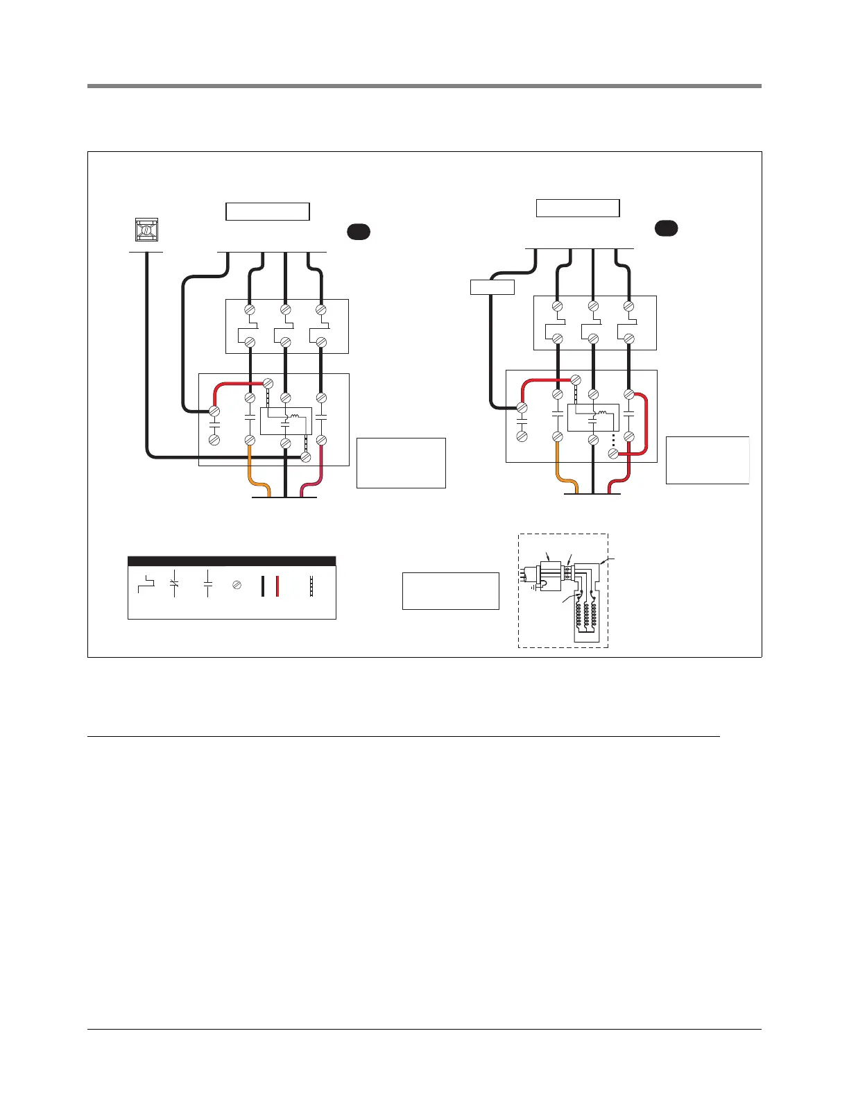
Figure 15. Three Phase Pump Wiring Diagram Examples
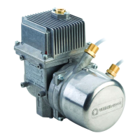
Connecting to the External Equipotential Bonding Terminal
A M6 threaded fastener set is provided on the side of the manifold underneath the double siphon port facility (see
Figure 16). Connection is to be in accordance with nationally applicable installation regulations using a conductor
having a cross-sectional area of at least 4mm
2
(10 AWG).
Orange
Red
Black
L1
L1
L1 L2NL3
L2
L2
L3
L3
To 380-415V Supply
240 V
Isotrol
240 V Coil
Contactor
For Remote
Control
Manual Motor
Protector
See Appendix C
Manual Motor
Protector
See Appendix C
COIL
3
2
A
To STP
NOTE: Contactor is
wired for 380-415V
to pump motor,
240V from Isotrol or
dispenser switch.
Make ground connection
in accordance with local
codes.
TB1
AT G
LEGEND
Bi-Metallic
switch
Normally
closed
contact
Normally
open
contact
Screw
terminal
Wire added
by installer
Wire added
by manufacturer
Electrical
interlock
On-winding
overload
protectors
Extractable
packer
Junction box
in manifold
Motor
STP
R
O
G
Orange
Red
Black
L1
L1
L1 L2NL3
L2
L2
L3
L3
To 380-415V Supply
240 V Coil
Contactor
For Remote
Control
COIL
3
2
B
To STP
NOTE: Contactor is
wired for 380-415V
to pump motor,
240V to dispenser
switch.
Dispenser
The ATG terminal will be the
same voltage and phase as
the power supplied to the L1
terminal.