Introduction Specifications
11
Distance between centerline of UMP and centerline of bottom fill tube should be 3 feet (914
mm) minimum. Air locking of pump after product delivery may occur at distances less than
this.
Specifications
Table 2 shows the adjustable pump lengths by model
Table 3 shows pump electrical service requirements.
Table 4 lists UMP weights and lengths and Table 5 lists pump shut off pressures.
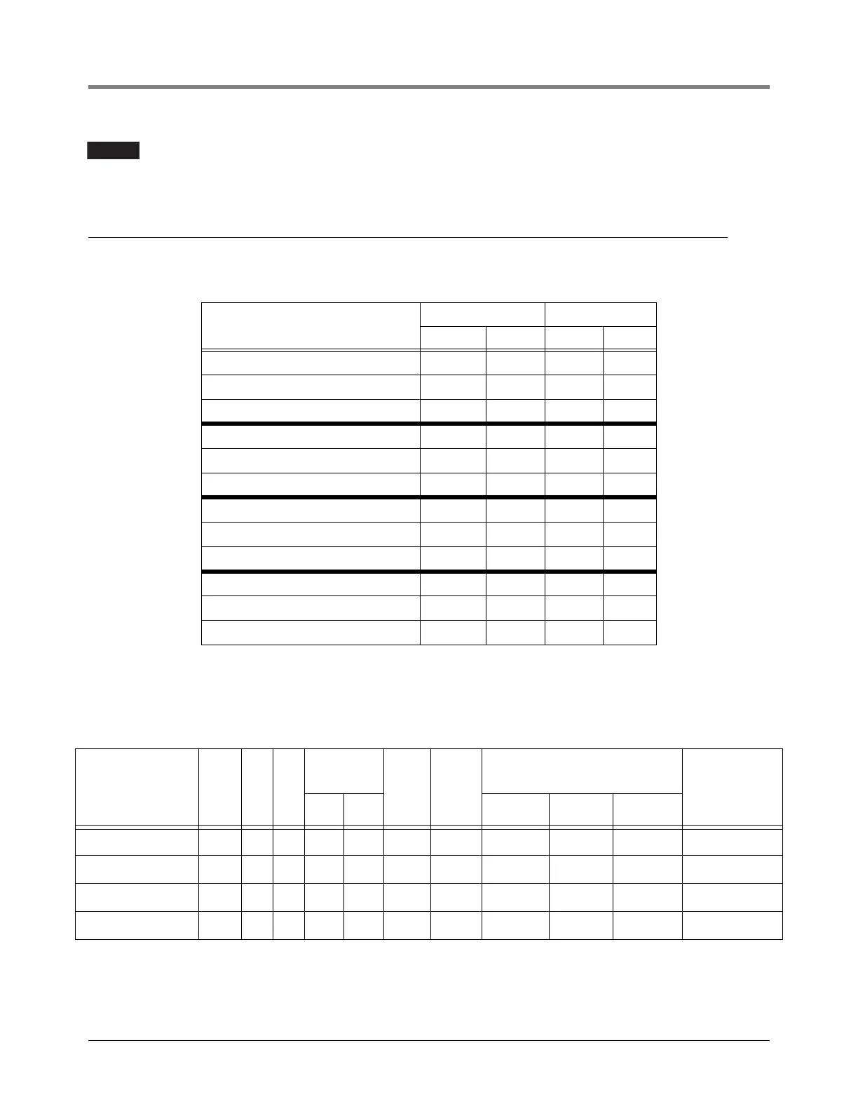
Table 2. Distances From Top Of Lifting Screw To Inlet
Model#
Retracted Extended
in. mm in. mm
AGP75S17-3RJ1, P75U17-3RJ1 73.0 1853 103.5 2624
AGP75S17-3RJ2, P75U17-3RJ2 103.0 2615 163.5 4148
AGP75S17-3RJ3, P75U17-3RJ3 163.0 4139 223.5 5672
AGP150S17-3RJ1, P150U17-3RJ1 75.0 1903 105.5 2674
AGP150S17-3RJ2, P150U17-3RJ2 105.0 2665 165.5 4198
AGP150S17-3RJ3, P150U17-3RJ3 165.0 4189 225.5 5722
X4AGP150S17RJ1, X4AGP150U17RJ1 75.5 1917 106.0 2688
X4AGP150S17RJ2, X4AGP150U17RJ2 105.5 2679 166.0 4212
X4AGP150S17RJ3, X4AGP150U17RJ3 165.5 4203 226.0 5736
AGP200S17-4RJ1, P200U17-4RJ1 77.5 1975 108.0 2745
AGP200S17-4RJ2, P200U17-4RJ2 107.5 2735 168.0 4270
AGP200S17-4RJ3, P200U17-4RJ3 167.5 4260 228.0 5790
Table 3. Electrical Service Information
Required power supply rating for 3 phase pumps, required rating is 380 - 415 Vac.
UMP Model No. HP Hz PH
Voltage
Fluctuation
Range
Max.
Load
Amps
Locked
Rotor
Amps
Winding Resistance (Ohms)
Setting on Motor
Protection DeviceMin. Max.
Black-
Orange
Red-
Orange Black-Red
AGUMP75S17-3,
UMP75U17-3
3/4 50 3 342 457 2.2 8.1 24.4 - 29.6 24.4 - 29.6 24.4 - 29.6 1.8
AGUMP150S17-3,
UMP150U17-3
1-1/2 50 3 342 457 3.8 14.1 12.1 - 14.7 12.1 - 14.7 12.1 - 14.7 3.8
X4AGUMP150S17,
X4UMP150U17
1-1/2 50 3 342 457 3.8 14.1 12.1 - 14.7 12.1 - 14.7 12.1 - 14.7 3.8
AGUMP200S17-4,
UMP200U17-4
2 50 3 342 457 5.0 17.7 9.9 - 12.0 9.9 - 12.0 9.9 - 12.0 4.5