Installation Wiring Three Phase Tandem Pumps
23
Wiring Three Phase Tandem Pumps
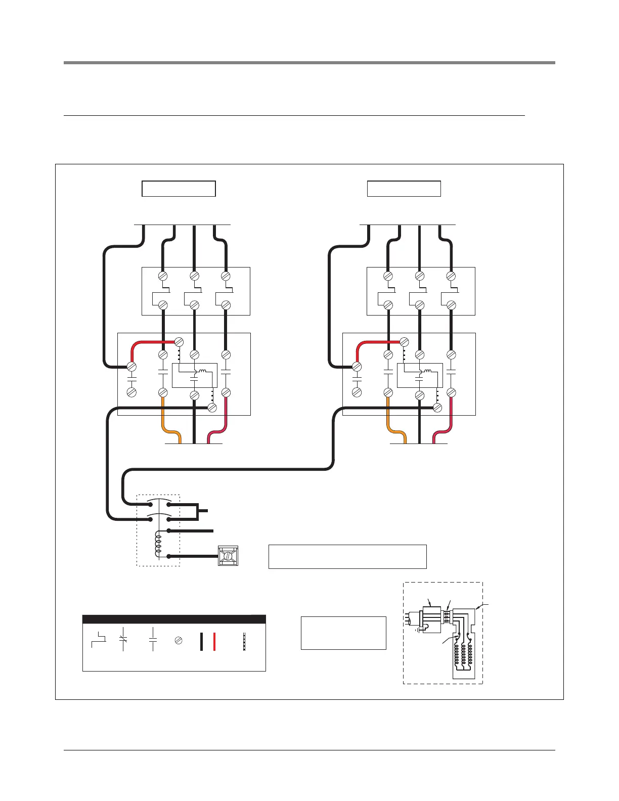
Figure 18 shows the wiring schematic which allows both three phase STPs to operate simultaneously with any
combination of dispensers turned on.
Figure 18. Suggested Wiring For Three Phase Tandem Pumps
240 V
Isotrol
Make ground connection
in accordance with local
codes.
TB1
AT G
LEGEND
Bi-Metallic
switch
Normally
closed
contact
Normally
open
contact
Screw
terminal
Wire added
by installer
Wire added
by manufacturer
Electrical
interlock
On-winding
overload
protectors
Extractable
packer
Junction box
in manifold
Motor
STP
R
O
G
The ATG terminal will be the same voltage and
phase as the power supplied to the L1 terminal.
Orange
Red
Black
L1
L1
L1 L2NL3
L2
L2
L3
L3
To 380-415V Supply
240 V Coil
Contactor
For Remote
Control
Manual Motor
Protector
See Appendix C
Manual Motor
Protector
See Appendix C
COIL
3
2
To STP
Orange
Red
Black
L1
L1
L1 L2NL3
L2
L2
L3
L3
To 380-415V Supply
240 V Coil
Contactor
For Remote
Control
COIL
3
2
To STP
2 Pole Relay
(240V Coil)
L1 (380-415V)
Neutral of Power Supply