Installation Testing the Line
29
Testing the Line
Disconnect, lock out, and tag power at the panel before servicing the
pump.
When servicing equipment, use non-sparking tools and use caution when removing or
installing equipment to avoid generating a spark.
Equipment required:
• Pressure generating equipment with appropriate fittings to connect to the 1/4’’ NPT line test port
Procedure
1. Block lines at each dispenser.
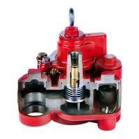
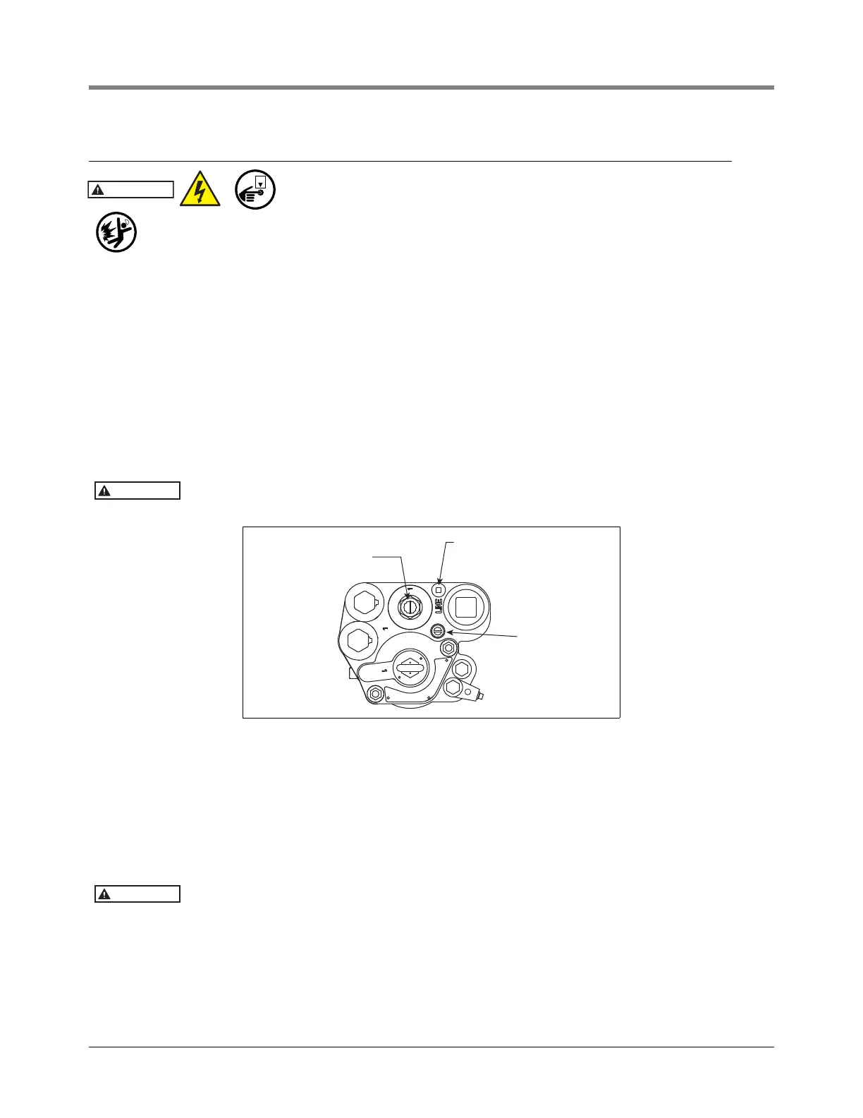
2. Remove and retain the protective plug over the service screw and turn the screw clockwise (see Figure 23).
As the screw approaches its bottom position, you will hear the system depressurizing. Continue turning the
screw until it can go no further.
3. Remove line test port plug (see Figure 24). Apply line test pressure at line test port (50 psi [345 kPa]
maximum).
Excessive pressure (above the normal test pressure of 50 - 55 psi [345 - 380 kPa]) may
damage check valve seat and other system components.
Figure 24. Service Screw, Line Test Port, And Air Purge Screw Locations
4. Depressurize the line (as per Step 2 above) and remove test fixture. Apply an adequate amount of fresh, UL
classified for petroleum, non-setting thread sealant on the 1/4’’ NPT plug and replace it in the line test port.
Torque the plug to 14 to 21 ft-lbs (19.4 to 29 N•m).
5. Turn the service screw counterclockwise all the way up. As the screw nears its top position you will hear the
check valve drop into position. Replace the protective plug over the service screw and fully thread into place
to ensure a good seal.
6. Turn the air purge screw 2 - 3 turns counterclockwise (see Figure 24).
The air purge screw is retained by a hitch pin to limit travel. Do not attempt to rotate
beyond 3 turns.
7. Turn the pump on and let it run for about 2 minutes to purge air from the manifold’s hydraulic cavities. While
the pump is still running, turn the air purge screw clockwise until it is completely closed.
8. The pump is now ready for normal operation.
9. If applicable, unblock lines at each dispenser.
Unscrew protective plug to
access service screw
Line test port
Air purge screw
rjpumps/fig21.eps