Table of Contents
iv
Replacing the Check Valve Assembly ............................................................................34
Kits Required:.........................................................................................................34
Procedure: ..............................................................................................................34
Replacing the Conduit Bushing ......................................................................................36
Parts Required:.......................................................................................................36
Procedure: ..............................................................................................................36
Replacing the Pigtail .......................................................................................................37
Kits Required:.........................................................................................................37
Procedure: ..............................................................................................................37
Replacing the Packer-to-Manifold Wiring Connectors ....................................................40
Kits Required:.........................................................................................................40
Procedure: ..............................................................................................................40
Replacing the Air Purge Screw .......................................................................................45
Kits Required:.........................................................................................................45
Procedure: ..............................................................................................................45
Parts Lists
Customer Service Number ..............................................................................................49
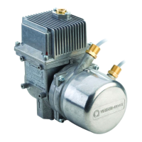
Pump Parts .....................................................................................................................49
Siphon Cartridge Kit Parts ..............................................................................................51
Check Valve Housing Kit Parts .......................................................................................51
Check Valve Kit Parts .....................................................................................................52
Conduit Bushing Kit Parts ...............................................................................................52
Hardware/Seal Kit Parts .................................................................................................53
Electrical Connector Kit Parts .........................................................................................54
UMP Wire Termination And Sealing Kit Parts .................................................................54
Die Spring Kit Parts ........................................................................................................55
Air Purge Screw Kit Parts ...............................................................................................56
Appendix A: Check Valve/Air Purge Screw Operation
Appendix B: Hardware/Seal Kit O-Ring Gauge
Appendix C: Settings For Motor Protection Device
Figures
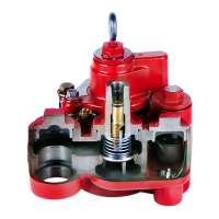
Figure 1. Red Jacket Packer/Manifold Components And Dimensions ..................8
Figure 2. FLoating Suction Installation ...................................................................9
Figure 3. Floating Suction Adapter ........................................................................9
Figure 4. Measuring The Tank (See Table 2 For Adjustment Ranges). ..............10
Figure 5. Packer/Manifold With Piping Attaching To UMP ...................................13
Figure 6. Verifying Pigtail’s Female Connector Is Seated Properly .....................14
Figure 7. Aligning The UMP Gasket ....................................................................14
Figure 8. Measuring Tank ....................................................................................15
Figure 9. Loosening Locking Nut .........................................................................16
Figure 10. Adjusting Pump Length .........................................................................16
Figure 11. Locating Return Line Fitting On Packer ................................................17
Figure 12. Attaching Return Line Tubing To Pump ................................................17
Figure 13. Connecting UMP To Packer Wiring ......................................................19
Figure 14. Power Wiring Enters Through Compression Bushing ..........................20
Figure 15. Three Phase Pump Wiring Diagram Examples ....................................21
Figure 16. Equipotential Bonding Terminal ............................................................22
Figure 17. Tandem Pumps ....................................................................................22