Replacing the CPU Board Removing the CPU Board
9
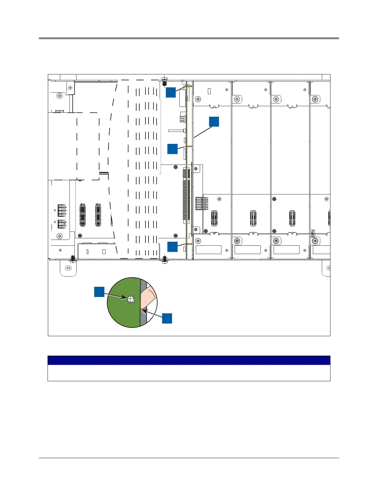
3. Locate the three retention snap pins along the front of the CPU board (see Figure 7).
Figure 7. Locating CPU board hold-down pins
4. Remove the grounding wrist strap (Part No. 576010-908) from its package and wrap one end around your
wrist. Adhere the other end to the metal plate on the inside of the Printer door.
5. Disconnect the four cables from the Display door along the front edge of the CPU board (sse Figure 8).
6. Position your forefinger beneath one of the pins and press up releasing the CPU board (see item 3 in
Figure 7). Repeat at each of the remaining two retention pins.
LEGEND FOR NUMBERED BOXES IN Figure 7
1. Board retention snap pins
2. Compartment bulkhead.
3. At each retention pin, slide forefinger in between board and
bulkhead and pry board away from bulkhead to release pin.
RELAY RATINGSRELAY RATINGS
240 VAC, 2 A MAX240 VAC, 2 A MAX
24 VDC, 2 A MAX24 VDC, 2 A MAX
WARNING: TO MAINTAIN
INTRINSIC SAFETY, ALL
COVERS MUST BE IN
PLACE.
WARNING: TO MAINTAIN
INTRINSIC SAFETY, ALL
COVERS MUST BE IN
PLACE.
WARNING: TO MAINTAIN
INTRINSIC SAFETY, ALL
COVERS MUST BE IN
PLACE.
WARNING: TO MAI
INTRINSIC SAFETY
COVERS MUST BE
PLACE.
1
1
1
954-8.eps
2
3
1
 Loading...


