Replacing the CPU Board Removing the CPU Board
10
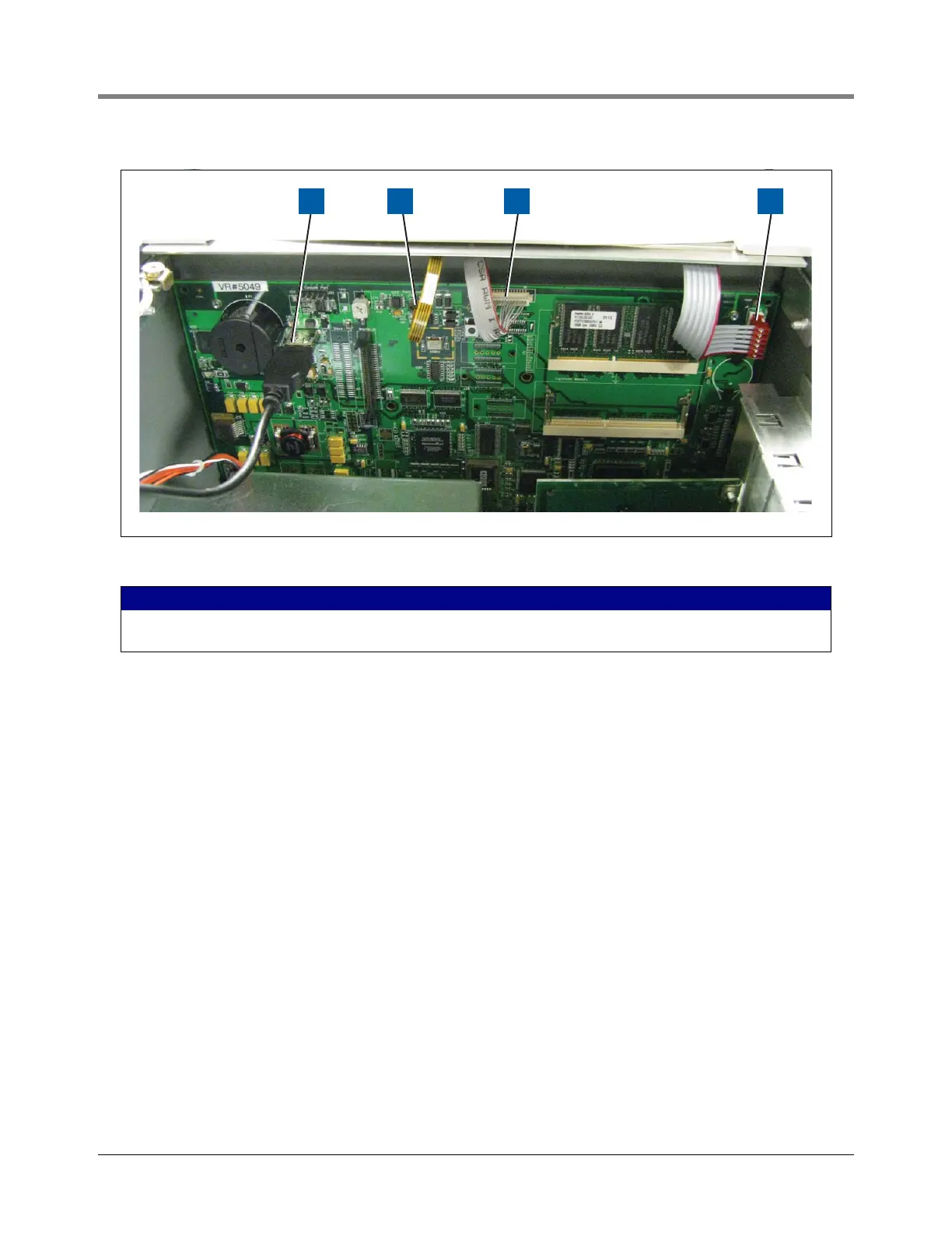
Figure 8. Cable connections to CPU board
7. Tilt the board a little away from the bulkhead (item 2 in Figure 7) and grasping the edge of the board pull out
firmly to remove the board from its backplane board connector. Once the CPU board is free from the
connector, slowly remove the board from the console being careful not to hit the CF card against the door.
8. Place the old and new CPU boards side by side on a clean work surface.
9. Remove the iButton from the old CPU board and install it in the same socket on the new CPU board (see
Figure 9). Make sure the flanged side of the iButton is up in its socket (see Figure 10).
10. Remove the CF card from the old board and install it in the same connector on the new CPU board. Orient
the CF card so the large/small grooves in the side of the CF card align with large/small guides on the sides of
the connector (see Figure 11).
11. Remove the RAM board by pushing the retaining clips away from the notches in the side of the RAM board
allowing it to spring up about 30 degrees from the CPU board (see Figure 12). When board springs up it
may be removed (handle the RAM board by its edges). Place the RAM board in the same (top) connector on
the new CPU board, aligning the notch in the board’s connector edge over the rib in the CPU RAM board
connector. Push the RAM board in at a slight angle to seat the connector, then gently push down on the RAM
board until the retention clips snap into the notches in both edges of the RAM board (see Figure 12).
12. Once the iButton, CF card and RAM board are installed in the new CPU board, lift the CPU board by its
outer corners and slide the board into the console until the CPU board connector is entering the backplane
board’s connector, then push firmly down to seat the CPU board in the connector.
13. Make sure the holes in the CPU board for the three retention pins are aligned over the three pins. With your
thumb, push against the CPU board at each retention pin until they are all snapped into place.
LEGEND FOR NUMBERED BOXES IN Figure 8
1. USB printer cable
2. Touch screen control cable
3. Display data cable
4. LED/display cable
 Loading...


