TLS-IB Site Prep Manual European Probe and Riser Installation Criteria (Non-PTB)
9
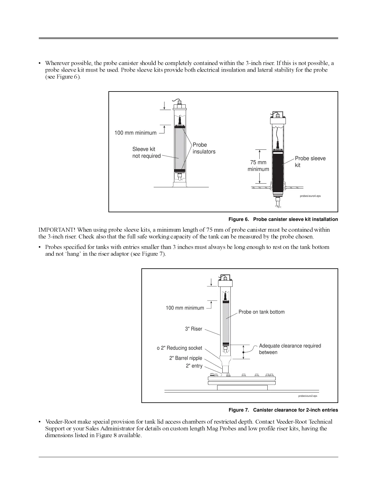
• Wherever possible, the probe canister should be com pletely contained within the 3-inch riser. If this is not possible, a
probe sleeve kit must be used. Probe sleeve kits provide both electrical insulation and lateral stability for the probe
(see F ig u re 6).
Figure 6. Probe canister sleeve kit installation
IMPORTANT! When using probe sleeve kits, a minimum length of 75 mm of probe canister must be contained within
the 3-inch riser. Check also t hat the full safe working capacity of the tank can be measured by the probe chosen.
• Probes specified for tanks with entries smaller than 3 inches must always be long enough to rest on the tank bottom
and not ‘hang’ in the riser adaptor (see Figure 7).
Figure 7. Canister clearance for 2-inch entries
• Veeder-Root make special provision for tank lid access chambers of restricted depth. Contact Veeder-Root Technical
Support or your Sales Administrator for details on custom length Mag Probes and low profile riser kits, having the
dimensions listed in Figure 8 available.
00 mm minimum
probes\euro4.eps
Probe sleev
kit
Sleeve kit
not required
Probe
insulators
75 mm
minimum
Probe on tank bottom
3" Riser
Adequate clearance required
between base of probe caniste
and adaptor reduction.
" to 2" Reducing socket
2" Barrel nipple
2" entry
100 mm minimum