TLS-IB Site Prep Manual Probe Wiring Safety Issues
18
•
Cro u se-H i n ds Co . - GR F X-139 jun ct io n box , G R F -10 cov er, a n d G A SK-643 gask e t.
Probe Wiring Safety Issues
Wiring between the TLS-IB and the probes is of limited electrical power so that there is insufficient energy to ignite fuel.
In the TL S-IB, the low power probe wiring is considered intrinsically safe because it is physically isolated from all high
power wiring. To maintain the integrity of this safety feature probe wiring can not share the same conduit with power
wiring. In addition, probe cables can only enter the TLS-IB through the designated intrinsically safe area knockouts.
If the TL S-IB is being retrof itted into a paved site, y ou can cut grooves in the pavement, run direct burial cable to the
probes, and then seal over the cable grooves.
Before trenching, you should diagram all conduit runs between the TLS-IB’s intended location and its deployed probes.
Your site diagram will help you calculate conduit and wiring lengths, and necessary quantities of junction boxes, sealing
boxes, clamps, brackets, etc.
Throughout this planning process and in the actual installation, you must follow all latest National Electric Codes, and
applicable federal, state, and local codes as regards conduit type, depth below grade, sealing, grounding, wire capacities,
direct burial (if permitted), etc.
Probe Manhole Installation
At each underground probe location, install a 14-inch minimum diameter approved manhole according to the
manufacturer’s instructions (Note: probes should be located at least 24 inches from the submersible pump to avoid
erroneous probe readings when the pum p is running).
Position the manhole so that there is necessary clearance for junction box installation and wiring.
Various Mag Probe Kits are required to install Mag probes in a dedicated riser of an underground (UST) or above ground
(AST) tank. Verify that you have the necessary kits for your application, and that you have all of the listed components,
before beginning the Mag probe installation.
Determining Length of Probe When Used in a Dedicated Riser
Perform the following procedure to ensure that probes are installed in the proper tanks [Figure 13]. Inaccurate readings
will result if probes are not the correct length for the given tank diameter. If tank diameter is unknown, perform the
following procedure:
1. Measure the distance from the bottom of the tank to the top of the probe riser pipe (A).
2. M easure the distance from the bottom of the probe riser pipe to the top of the probe riser pipe (B).
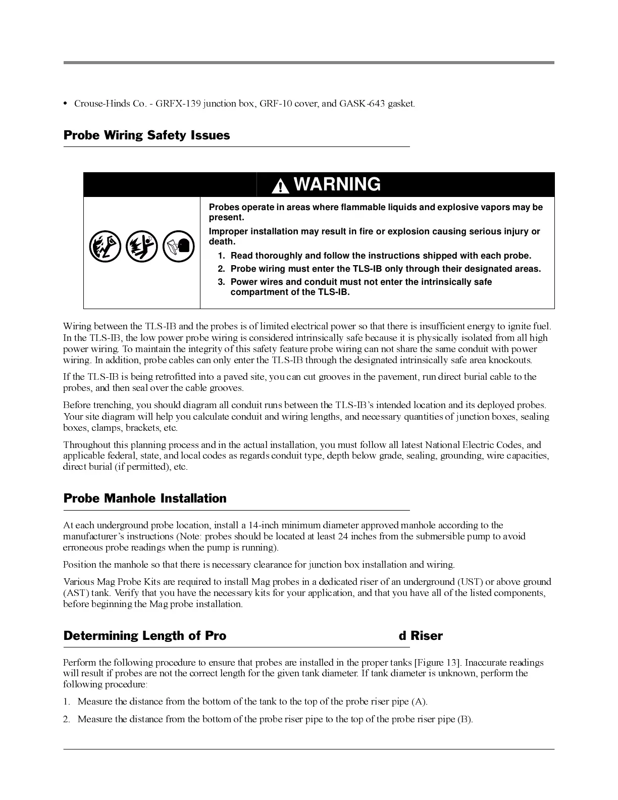
WARNING
Probes operate in areas where flammable liquids and explosive vapors may be
present.
Improper installation may result in fire or explosion causing serious injury or
death.
1. Read thoroughly and follow the instructions shipped with each probe.
2. Probe wiring must enter the TLS-IB only through their designated areas.
3. Power wires and conduit must not enter the intrinsically safe
compartment of the TLS-IB.