TLS-IB Site Prep Manual Probe Conduit Installation
25
Probe Conduit Installation
Buried Rigid Conduit
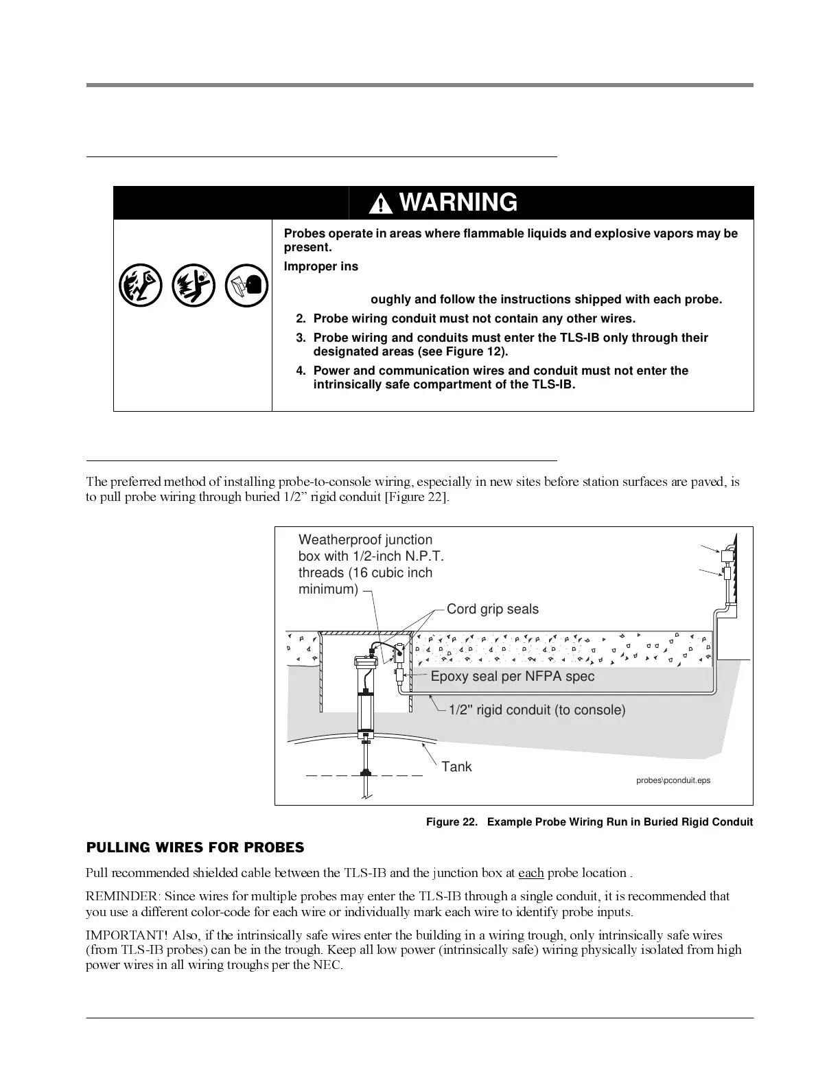
The preferred method of installing probe-to-console wiring, especially in new sites before station surfaces are paved, is
to pull probe wiring through buried 1/2” rigid conduit [Figure 22].
Figure 22. Example Probe Wiring Run in Buried Rigid Conduit
PULLING WIRES FOR PROBES
Pull recom mended shielded cable between the TL S-IB and the junction box at each probe location .
REMINDER: Since wires for multiple probes may enter the TLS-IB through a single conduit, it is recommended that
y ou use a different color-code for each wire or individually mark each wire to identify probe inputs.
IMPORTANT! Also, if the intrinsically saf e wires enter the building in a wiring trough, only intrinsically saf e wires
(from TLS-IB probes) can be in the trough. Keep all low power (intrinsically safe) wiring physically isolated from high
power wires in all wiring troughs per the NEC.
WARNING
Probes operate in areas where flammable liquids and explosive vapors may be
present.
Improper installation may result in fire or explosion causing serious injury or
death.
1. Read thoroughly and follow the instructions shipped with each probe.
2. Probe wiring conduit must not contain any other wires.
3. Probe wiring and conduits must enter the TLS-IB only through their
designated areas (see Figure 12).
4. Power and communication wires and conduit must not enter the
intrinsically safe compartment of the TLS-IB.
Cord grip seals
Weatherproof junction
box with 1/2-inch N.P.T.
threads (16 cubic inch
minimum)
Epoxy seal per NFPA spec
probes\pconduit.eps
1/2'' rigid conduit (to console)
Tank
.
.
.
.
.
..
.
.
.
.
.
.
.
.
.
.
.
.
.
.
.
.
.
.
..
.
.
.
.
.
.
.
.
.
.
..
.
.
.
.
.
.
.
.
.
.
.
.
..
.
.
.
.
.
.
.
.
.
.
.
.
..
.
.
.
.
.
.
.
.
.
.
.
.
.
.
.
.
.
.
..
.
.
.
.
.
.
.
.
.
.
.
.
.
.
.
.
.
.
.
.
.
.
.
.
.
.
.
.
.
.
.
.
.
.
.
.
.
.
.
.
.
.
.
.
.
.
.
.
.
.
.
.
.
.
.
.
.
.
.
.
.
.
.
.
.
.
.
.
.
.
.
.
.
.
.
.
.
.
.
.
.
.
.
.
.
.
..
.
.
.
.
.
.
.
Seal-Off
Splice Closure