TLS-IB Site Prep Manual Connecting Serial Communication Wiring to the TLS-IB
31
IMPORTANT! If the TLS-IB is not a terminating device on the IFSF netw ork, y ou must remove the LON cable ter-
mination jumper (JP3) from the board. Failure to do so will result in improper operation.
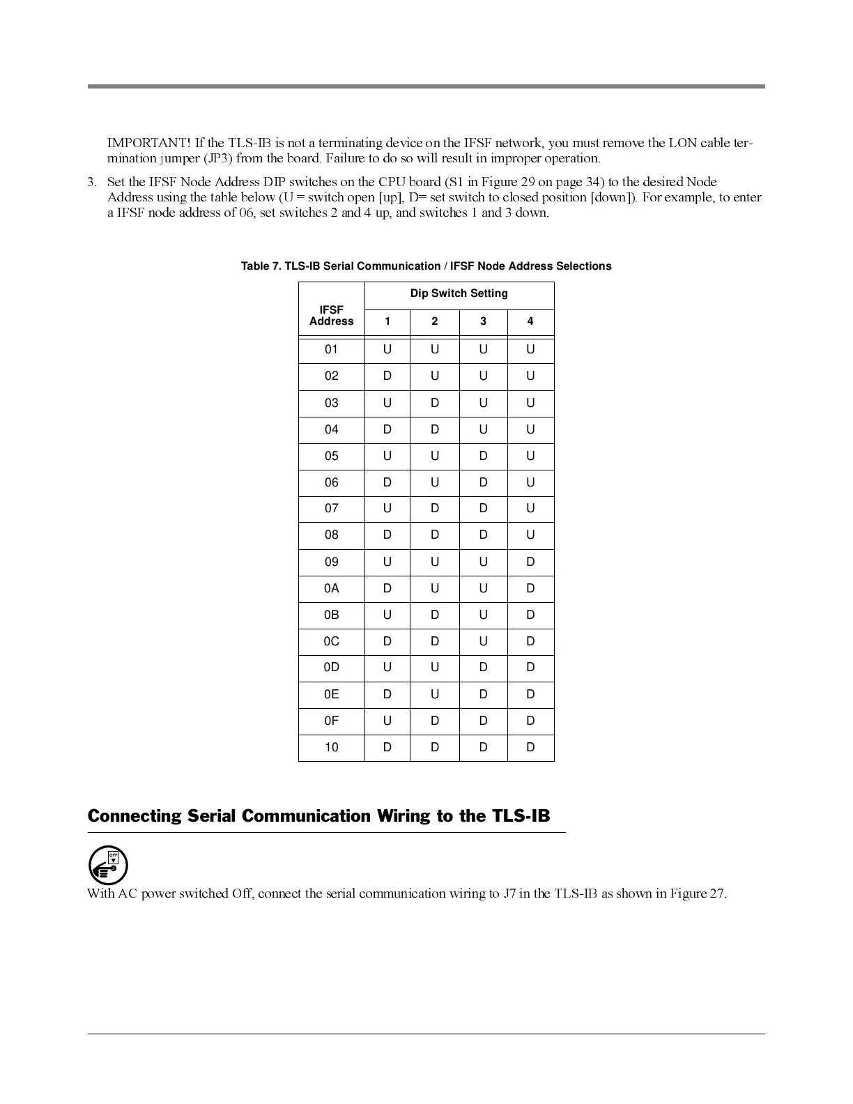
3. Set the IFSF Node Address DIP switches on the CPU board (S1 in Figure 29 on page 34) to the desired Node
Address using the table below (U = switch open [up], D= set switch to closed position [down]). For example, to enter
a IFSF node address of 06, set switches 2 and 4 up, and switches 1 and 3 do wn.
Connecting Serial Communication Wiring to the TLS-IB
With AC power switched Off, connect the serial communication wiring to J7 in the TLS-IB as shown in Figure 27.
Table 7. TLS-IB Serial Communication / IFSF Node Address Selections
IFSF
Address
Dip Switch Setting
1234
01 U U U U
02 D U U U
03 U D U U
04 D D U U
05 U U D U
06 D U D U
07 U D D U
08 D D D U
09 U U U D
0A D U U D
0B U D U D
0C D D U D
0D U U D D
0E D U D D
0F U D D D
10 D D D D
OFF