TLS-IB Site Prep Manual TLS-IB Location
13
To allow for maintenance ensure that the console is in an accessible area, even when the console doors are open.
IMPORTANT! If the unit requires cleaning, do not use any liquid materials (e.g. cleaning solvents). It is recommended
that the unit be wiped with a clean dry cloth when necessary.
Ensure that all relevant subcontractors and other personnel are aware of the selected location.
The TLS-IB is installed by Veeder–Root authorised engineers.
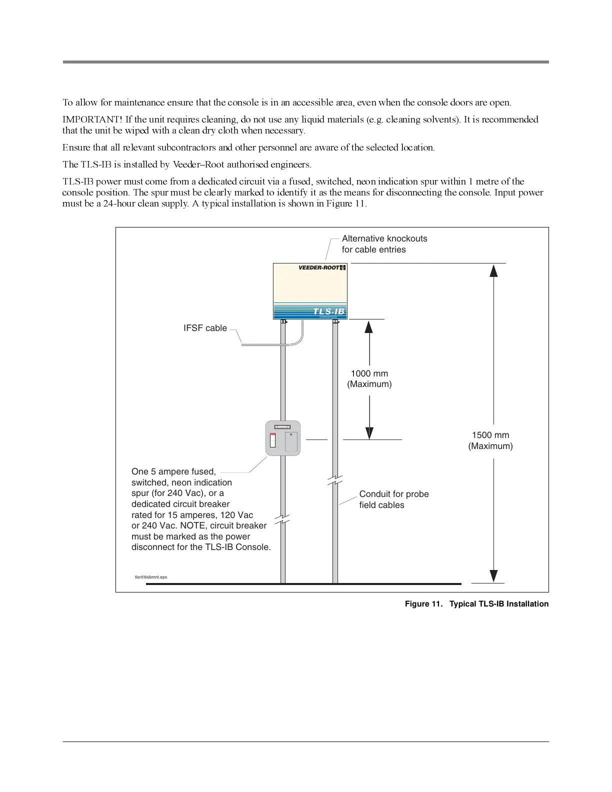
TLS-IB power must come from a dedicated circuit via a fused, switched, neon indication spur within 1 metre of the
console position. The spur must be clearly marked to identify it as the means for disconnecting the console. Input power
must be a 24-hour clean supply. A typical installation is shown in Figure 11.
Figure 11. Typical TLS-IB Installation
tlsnt\tlsibmnt.eps
1000 mm
(Maximum)
1500 mm
(Maximum)
One 5 ampere fused,
switched, neon indication
spur (for 240 Vac), or a
dedicated circuit breaker
rated for 15 amperes, 120 Vac
or 240 Vac. NOTE, circuit breaker
must be marked as the power
disconnect for the TLS-IB Console.
IFSF cable
Conduit for probe
field cables
Alternative knockouts
for cable entries
VEEDER-ROOT
INTERCONNECTION BOX
TLS-IB