TLS-IB Site Prep Manual Probe Riser Pipe Installation (Level 1 Installation Only)
10
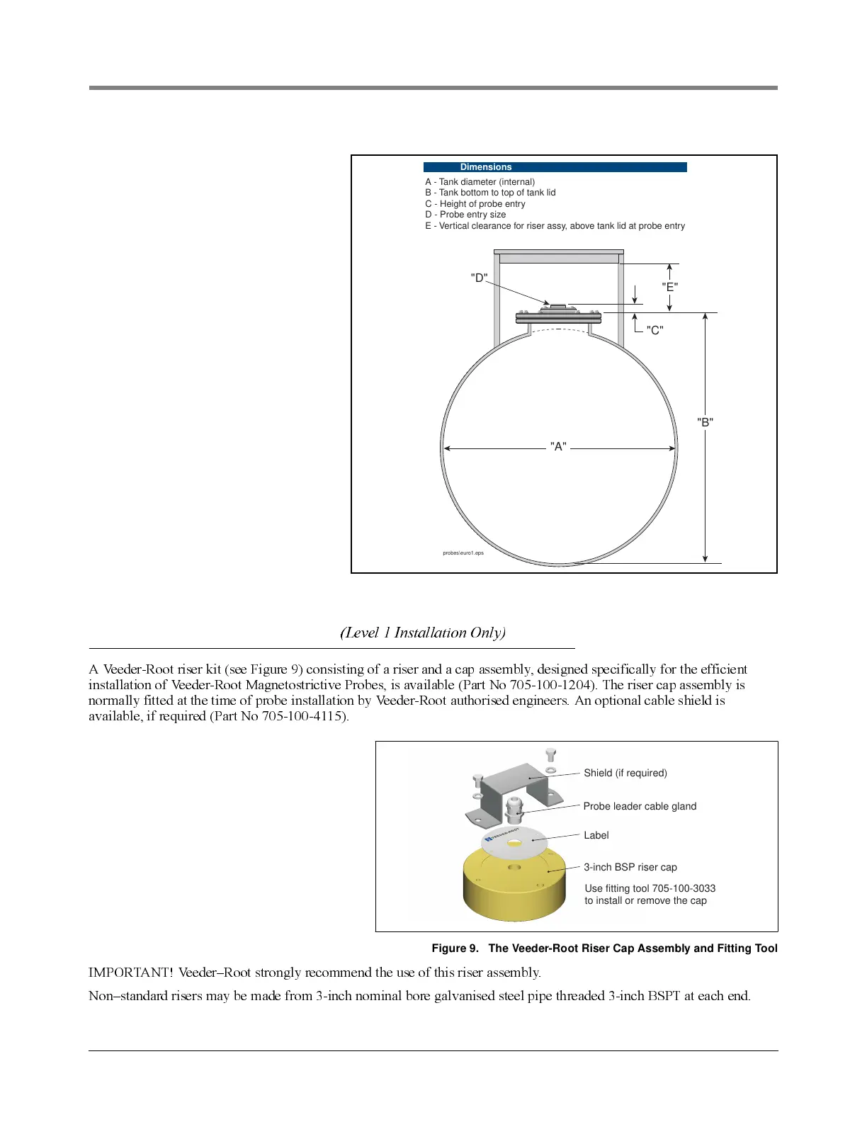
Figure 8. Dimensions needed to calculate custom probes and risers
Probe Riser Pipe Installation
(Level 1 Installation Only)
A Veed er-Ro o t rise r ki t (see Fig ure 9) co ns ist i ng of a rise r and a cap ass embly, d esi g n ed speci fic al ly for th e ef f i c ie nt
in sta l la ti o n o f Ve ed e r-Roo t Mag n e to st ric ti v e Probe s, is ava il abl e (Part No 705-100-1204). The riser ca p assembl y is
normally fitted at the time of probe installation by Veeder-Root authorised engineers. An optional cable shield is
available, if required (Part No 705-100-4115).
Figure 9. The Veeder-Root Riser Cap Assembly and Fitting Tool
IMPORTANT! Veeder–Root strongly recommend the use of this riser assembly.
Non–standard risers may be made from 3-inch nominal bore galvanised steel pipe threaded 3-inch BSPT at each end.
"B"
"E"
"A"
"D"
"C"
probes\euro1.eps
A - Tank diameter (internal)
B - Tank bottom to top of tank lid
C - Height of probe entry
D - Probe entry size
E - Vertical clearance for riser assy, above tank lid at probe entry
Dimensions
Shield (if required)
Probe leader cable gland
Use fitting tool 705-100-3033
to install or remove the cap
3-inch BSP riser cap
Label