28
Connecting Wiring to the TLS-IB
Probe Wiring Precautions
To The Installer! You Must Read And Understand This Information. Reference manual number 577013-578 for
additional safety related information.
PROBE WIRING POSITIONS AND LABELING
In all cases, the devices wired to the TLS-IB’s input terminal blocks must be recorded to prevent improper
replacement during installation or service.
Wiring Assignments
1. Identify all probe wires according to their terminal block location using the self-adhesive numbering labels furnished.
Accurately record on the circuit directory label (top of I.S. compartment cover plate - see Figure 25), the tank number
of each probe
as you attach wires
to the probe input terminal block.
2. IMPORTANT! Once a device has been wired to certain terminals and the system has been programmed, the wires
from that device may not be relocated to other terminals without reprogramming the system.
Connecting Probes to the TLS-IB
Connect the two color-coded/marked wires from each probe to the appropriate connectors (e.g., Probe 1) of the Probe
Terminal Block as shown in Figure 25.
IMPORTANT! Observe polarity when connecting probe wires!
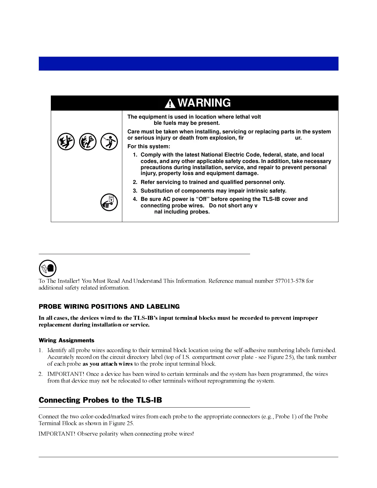
WARNING
The equipment is used in location where lethal voltages and explosive vapors
or flammable fuels may be present.
Care must be taken when installing, servicing or replacing parts in the system
or serious injury or death from explosion, fire or shock may occur.
For this system:
1. Comply with the latest National Electric Code, federal, state, and local
codes, and any other applicable safety codes. In addition, take necessary
precautions during installation, service, and repair to prevent personal
injury, property loss and equipment damage.
2. Refer servicing to trained and qualified personnel only.
3. Substitution of components may impair intrinsic safety.
4. Be sure AC power is “Off” before opening the TLS-IB cover and
connecting probe wires. Do not short any voltage across any barrier
terminal including probes.
OFF