TLS-IB Site Prep Manual Neuron Service Switch
38
4. The Power Supply board is secured by two T-15 Torx screws in the top of the board. After removing the Torx screws,
slowly lift up on the board until the lower tabs on the board clear the slots in the bottom of the TLS-IB, then continue
to lift the board out.
5. Replace the board by reversing the above steps.
6. Switch On power to the TLS-IB and check your system configuration for proper setup.
Neuron Service Switch
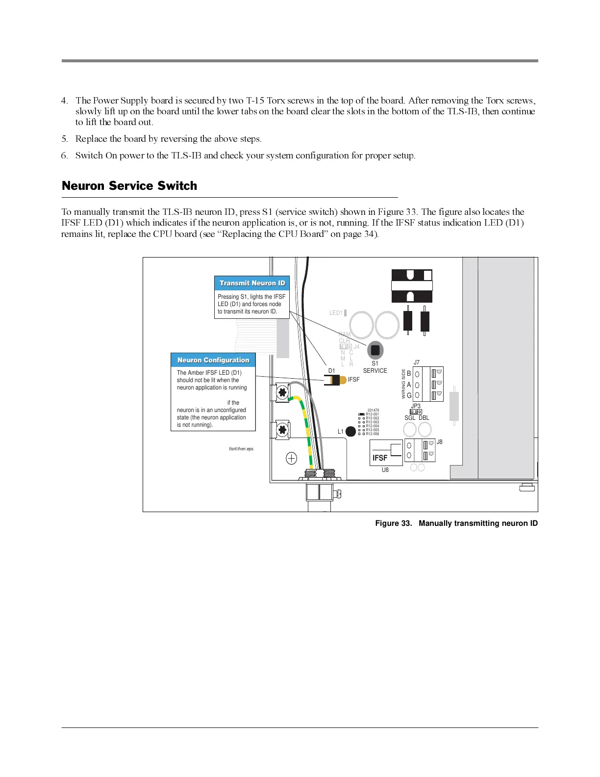
To manually transmit the TLS-IB neuron ID, press S1 (service switch) shown in Figure 33. The figure also locates the
IFSF L E D (D1) which indicates if the neuron application is, or is not, running. If the IFSF status indication LED (D1)
remains lit, replace the CPU board (see “Replacing the CPU Board” on page 34).
Figure 33. Manually transmitting neuron ID
SGL DBL
B
A
WIRING SIDE
G
J4
D1
LED1
IFSF
JP3
J8
U8
J7
L1
S1
SERVICE
RAM
tlsnt\ifver.eps
IFSF
CLR
N
M
L
C
L
R
R12-001
331470
R12-002
R12-003
R12-004
R12-005
R12-006
Pressing S1, lights the IFSF
LED (D1) and forces node
to transmit its neuron ID.
Transmit Neuron ID
Transmit Neuron ID
The Amber IFSF LED (D1)
should not be lit when the
neuron application is running.
This LED remains lit if the
neuron is in an unconfigured
state (the neuron application
is not running).
Neuron Configuration
Neuron Configuration