TLS-IB Site Prep Manual Replacing the Power Supply Board
37
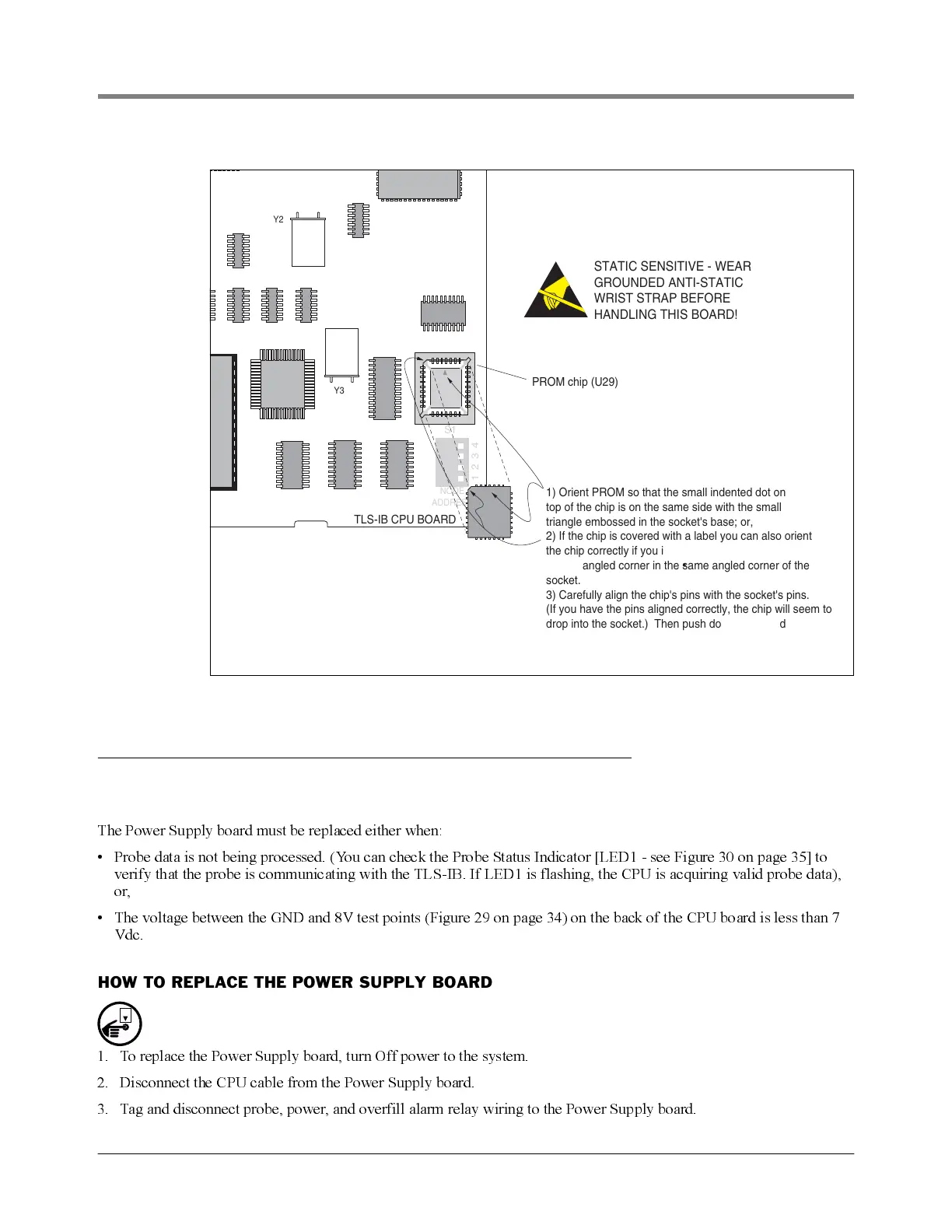
Figure 32. Replacing PROM Chip
Replacing the Power Supply Board
WHEN TO REPLACE THE POWER SUPPLY BOARD
The Power Supply board must be replaced either when:
• Probe data is not being processed. (You can check the Probe Status Indicator [LED1 - see Figure 30 on page 35] to
verify that the probe is communicating with the TLS-IB. If LED1 is flashing, the CPU is acquiring valid probe data),
or,
• The voltage between the GND and 8V test points (Figure 29 on page 34) on the back of the CPU board is less than 7
Vdc.
HOW TO REPLACE THE POWER SUPPLY BOARD
1. To replace the Power Supply board, turn Off power to the system.
2. Disconnect the CPU cable from the Power Supply board.
3. Tag and disconnect probe, power, and overfill alarm relay wiring to the Power Supply board.
Y2
NODE
ADDRESS
1234
Y3
TLS-IB CPU BOARD
PROM chip (U29)
S1
STATIC SENSITIVE - WEAR
GROUNDED ANTI-STATIC
WRIST STRAP BEFORE
HANDLING THIS BOARD!
1) Orient PROM so that the small indented dot on
top of the chip is on the same side with the small
triangle embossed in the socket's base; or,
2) If the chip is covered with a label you can also orient
the chip correctly if you insert the chip in the socket
with its angled corner in the same angled corner of the
socket.
3) Carefully align the chip's pins with the socket's pins.
(If you have the pins aligned correctly, the chip will seem to
drop into the socket.) Then push down firmly and evenly
on the chip until it snaps into the socket.
4) Check to see that all pins are in place and none are bent.
OFF