19
5 Connecting to power supply
VEGAPOINT 21 • Transistor (NPN/PNP)
56623-EN-210210
9. Tighten the screws on the strain relief and cable entry
10. Hook in the cover and push onto the plug connection, tighten
cover screw
11. Plug the plug insert with seal to VEGAPOINT 21 and tighten the
screw
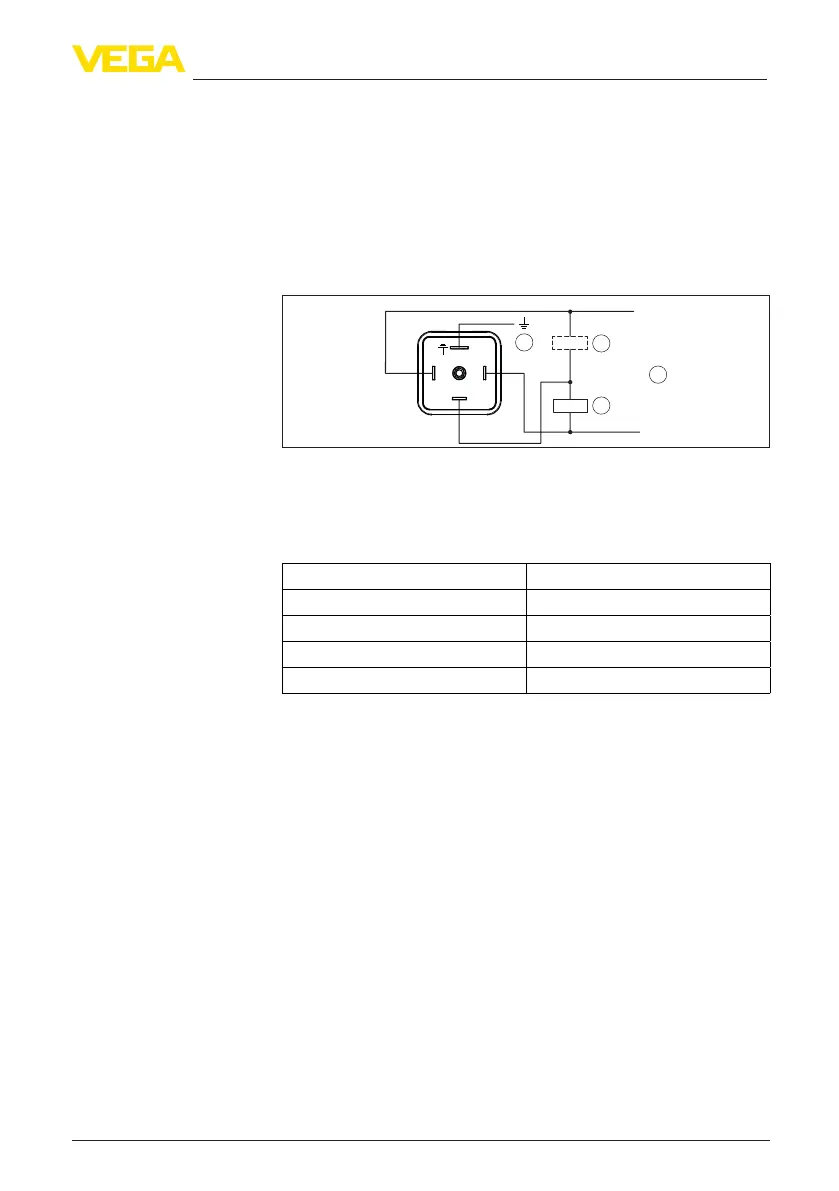
5.3 Wiring plan
For connection to binary inputs of a PLC.
1
3
4
2
12
3
+
-
Fig. 12: Wiring plan connector ISO 4400 - transistor output three-wire
1 Voltage supply
2 PNP switching
3 NPN switching
4 PA - Potential equalisation
Contact, plug connector Function/Polarity
1 Voltage supply/+
2 Voltage supply/-
3 Transistor output
4 PA - Potential equalisation
5.4 Switch-on phase
Afterswitchingon,thedevicerstcarriesoutaself-testinwhichthe
function of the electronics is checked.
The current measured value is then output on the signal cable.
Valve plug ISO 4400