22
7 Setup
VEGAPOINT 21 • Transistor (NPN/PNP)
56623-EN-210210
7 Setup
7.1 Indication of the switching status
The switching status of the electronics can be checked via the 360°
status indication (LEDs) integrated in the upper part of the housing.
The colours of the 360° status indication have the following meaning:
1)
•
Green lights up - power supply connected, sensor output high-
impedance
•
Greenashing-Maintenancerequired
•
Yellow lights up - power supply connected, sensor output low
impedance
•
Red lights - shortcircuit or overload in the load circuit (sensor
output high-impedance)
•
Redashing-Erroratsensororelectronics(sensoroutputhigh
impedance) or device is in simulation
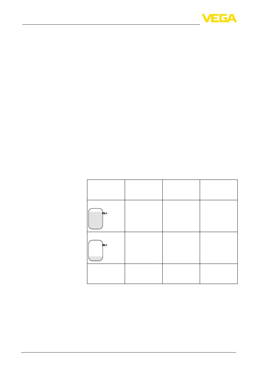
7.2 Function table
The following table provides an overview of the switching conditions
depending on the set mode and the level (factory setting).
The colours of the signal lamp correspond to the signalling according
to NAMUR NE 107.
Coverage Switching sta-
tus
2)
Output 1
Switching sta-
tus
3)
Output 2
360° status indi-
cation
4)
Covered open closed Green
Uncovered closed open Yellow
Fault
(Covered/Uncov-
ered)
open open Red
7.3 Menu overview
There are several ways to operate the device.
The Bluetooth version (optional) of the instrument enables a wireless
connection to standard adjustment units. This can be smartphones/
Adjustment possibilities
1)
Default setting
2)
Default setting
3)
Default setting
4)
Output 1