27
7 Setup
VEGAPOINT 21 • Transistor (NPN/PNP)
56623-EN-210210
FH
t
FL
off
on
off
on
A
B
1 1
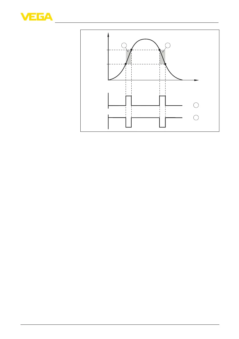
Fig. 14: Window function
FH Window high - upper value
FL Window low - lower value
A FNO (Window Normally Open) = Closing contact
B FNC (Window Normally Closed) = Opener
t Timeline
1 Window area
In this menu item, you can select the settings for the switching output.
This is only possible if User-dened was selected in the application.
In the function " Impedance curve" you can see the changes and the
position of the hysteresis.
•
Switching point (SP1)
•
Reset point (RP1)
•
Switching delay (DS1)
•
Reset delay (DR1)
Switching point (SP1)
The switching point (SP1) indicates the switching threshold of the
sensor related to the immersion depth or the degree of coverage.
Thepercentagedenesthelowerrangelimitofthehysteresis.
The setting is a degree for the sensitivity of the sensor tip.
Reset point (RP1)
The reset point (RP) controls the sensitivity of the sensor when the
sensor tip becomes free.
Thepercentagedenestheupperrangelimitofthehysteresis.
The setting is a degree for the sensitivity of the sensor tip.
Switching delay (DS1)
The switching delay (DS) extends the reaction time until the sensor is
switched over when the sensor tip is covered.
Switching output