Solar Pump Controller Manual
10
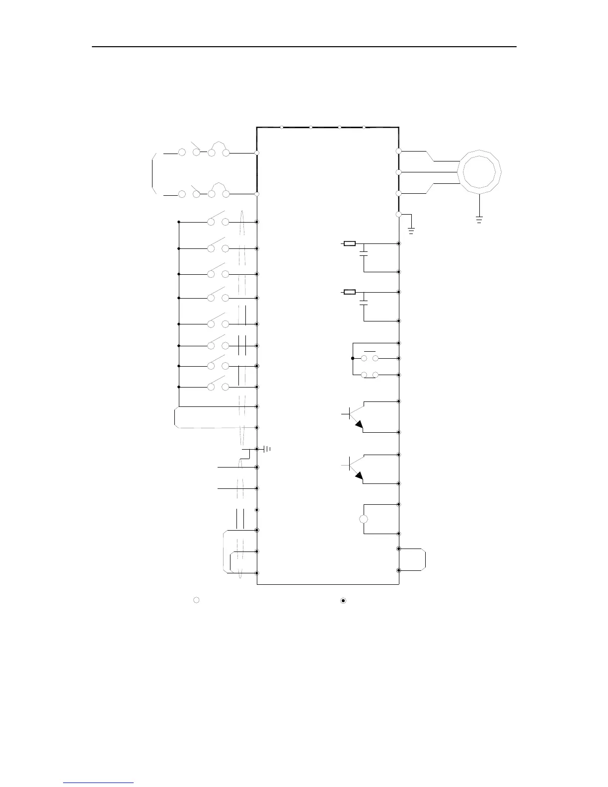
2.4 Solar pump controller wiring
The following diagram includs two parts:the main circuit and control circuit.
stand build-in RS485 module
for machine below 11G
-10V signal supply power
Grounding
Open set electrode output
Output signal 3
Output signal 2
max:50mA
max:50mA
communication
RS485
A+
B-
COM
Y2
Y1
COM
Open set electrode output
GND
A02
F-62 Selection output
Analog input
signal
+10V signal supply power
-10V
GND
Pulse frequency
PUL
REV
REV
X5
Electrical machine
M
V
W
U
Analog quantity output
10VDC-1mA DC voltage
2A/30VDC
3A/250VAC
Auxiliary power
Output signal 1(relay)
24VDC-200mA
PB
N(-)
P1
MCCB
S
T
R
A01
X1
X2
X3
GND
X4
COM
X6
E
FWD
Solar
DC
input
multi-function
input terminal
FWD
TC
TA
TB
+10V
VS2
VS1
+24
AS
COM
main circuit terminal
V
-10V-+10V
4-20mA
cotrol circuit terminal
Earth
 Loading...