OPERATIONAL CONTROLS
Operation - 28
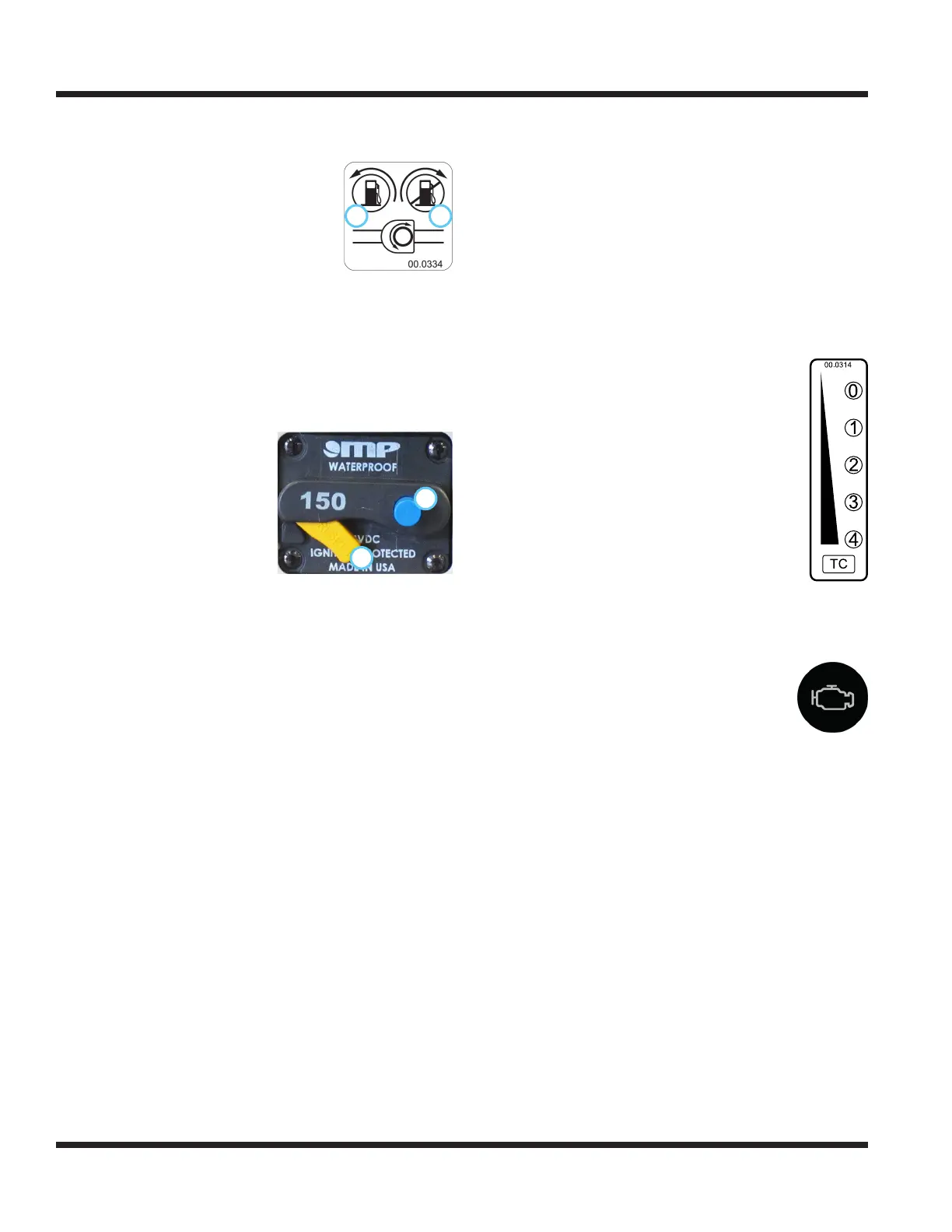
The fuel shut-o valve controls
1 0
the ow of fuel to the
power unit engine. Turn the valve
counterclockwise (1) to the stop to
allow fuel to ow to the engine.
Turn the valve clockwise (0) to the stop
to shut o fuel ow to prevent fuel
leakage when changing the fuel lters
or when servicing the fuel system.
Turn o the fuel shut-o valve when transporting the
power unit on a truck or trailer and when parking the
power unit indoors.
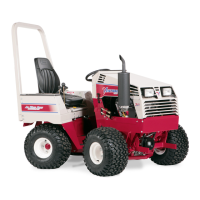
Circuit Breaker & Battery Disconnect (T)
The circuit breaker/battery disconnect switch controls
power to the entire electrical system.
1
0
0. Push to disengage power
1. Lift to restore power
Pushing the button (0) on the
switch disables the electrical
system, allowing electrical
components to be serviced.
When the button on the
switch is pushed to disen-
gage electrical power, a reset
lever (1) drops down from
the switch body. Lift up on
the reset lever to restore
electrical power.
Seat Prop Plate (U)
The seat prop plate secures the seat in the ipped for-
ward position while service is performed under the seat.
To secure, tilt the seat forward, lift up the seat prop
plate, and insert the end into the wide portion of the
seat plate slot. Ensure the seat prop plate snaps into
the narrow portion of the slot to prevent accidental
release.
To release, move the seat prop plate over into the
wide portion of the seat slot and tilt the seat forward.
Lower the seat prop plate back into the seat box and
lower the seat back down to the operating position.
Seat Strap Latch (V)
The seat latch strap secures the seat during transport
of the power unit.
To secure the seat, place the tab of the seat latch strap
over the seat latch pin. Install the linch pin through
the hole in the seat latch pin to secure.
To release the seat so that it can be tilted forward for
service, remove the linch pin and lift the tab of the
seat latch strap o the seat latch pin.
Weight Transfer Traction Control Select
Lever (W)
The weight transfer system transfers weight
from the attachment to the front wheels of
the power unit. Transferring weight from the
attachment to the power unit increases the
traction control, improves hillside maneuver-
ability, aids in lifting the attachment, reduces
the steering eort, and lessens the attach-
ment resistance when in contact with the
ground.
The operator can select dierent transfer
rates by selecting one of the ve positions
from no weight transfer (0) to maximum
weight transfer (4). Set the weight transfer to 0 when
attaching or detaching any attachment.
Engine Malfunction Indicator Light (Z)
If the engine malfunction indicator light
illuminates during use, contact your autho-
rized ventrac dealer to have a diagnostic
scan performed and the engine serviced.