SERVICE
Service - 56
Jump Starting Procedure
DANGER
The battery produces a ammable and explosive
gas. The battery may explode.
• Wear eye protection and gloves.
• Do not jump start a cold or frozen battery. Allow
the battery to warm up and inspect for cracks or
damage.
• Do not jump start a cracked or damaged bat-
tery.
• Do not attempt to jump start the power unit us-
ing a battery of a dierent voltage.
1. Inspect the discharged battery for terminal corro-
sion and loose connections. Clean the terminals
and tighten the connections prior to jump start-
ing.
2. Make sure the vehicle used to jump start the
power unit has a 12 volt, negative ground, electri-
cal system.
3. Pull the boosting vehicle up close to the disabled
power unit. Be sure the vehicles do not touch.
4. Shut o the boosting vehicle’s engine and engage
the parking brake.
ATTENTION
Attempting to start the disabled unit with the boost-
ing vehicle’s engine running could cause damage to
the regulator.
5.
7
8
6
5
2
4
3
1
A B C D E F G H I J K
1
2
3
4
B
A
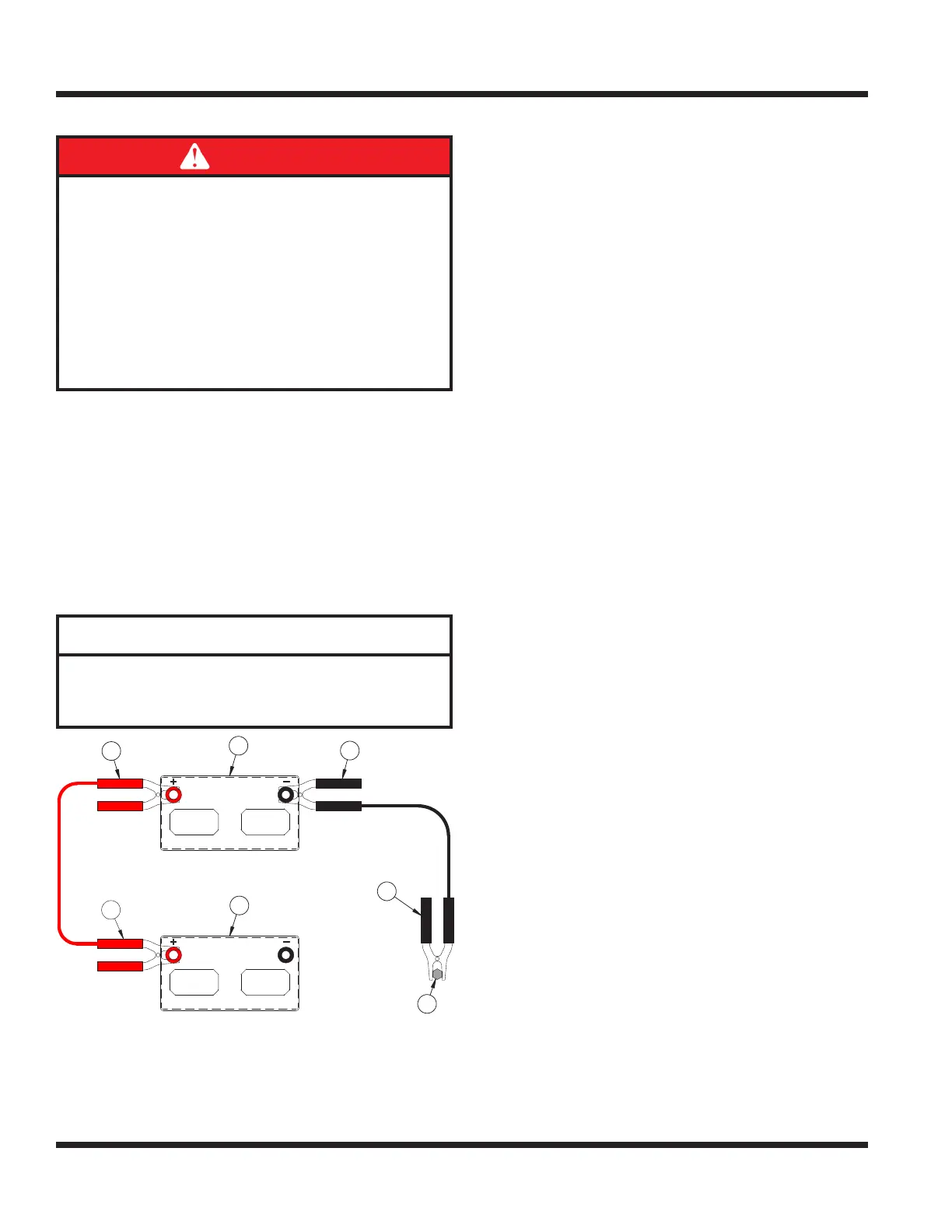
A. Discharged Battery
B. Booster Battery
C. Ground Stud
Connect one end of the positive (+) booster cable
to the positive (+) terminal (1) of the discharged
battery.
6. Connect the other end of the positive (+) booster
cable to the positive (+) terminal (2) of the boost-
er battery.
7. Connect the negative (-) booster cable to the
negative (-) terminal (3) of the booster battery.
8. Connect the other end of the negative (-) booster
cable to the disabled power unit’s ground stud (4).
9. Start the disabled power unit and remove the
booster cables in reverse order of installation
(negative booster cable rst).
TCM (Tractor Control Module) Explanation
The tractor control module controls the electronic
safety related functions of this power unit. Both solid
state and mechanical components are used to ensure
the safe, reliable operation of this machine.
This TCM monitors the electronic circuits necessary
for the engine, the starter, and the PTO to func-
tion. These input circuits include the PTO switch, the
neutral switch, the parking brake switch, the igni-
tion switch, and the seat switch. The TCM allows the
engine, the starter, or the PTO to operate only when
specic input criteria are satised. The engine, the
starter, and the PTO are controlled by outputs from
the TCM.