OPERATIONAL CONTROLS
Operation - 32
Seat Slide Lever (UU)
Lift up the seat slide lever to release the seat lock.
Move the seat forward or backward to the desired po-
sition and release the seat slide lever to lock the seat
in place.
1
0
2
2
1
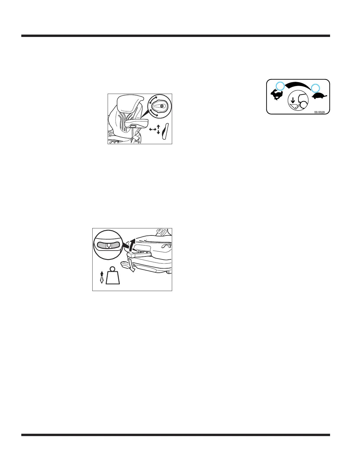
The lumbar support knob
adjusts the curvature of the
backrest in either the upper
or lower part of the backrest.
Position 0 provides minimal
support.
Position 1 provides maximum
curvature in the upper part of the backrest.
Position 2 provides maximum curvature in the lower
part of the backrest.
Backrest Angle Lever (WW)
Lift up the backrest angle lever to release the backrest
catch. Move the backrest to the desired position and
release the backrest angle lever to lock the backrest in
place.
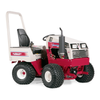
Weight Adjustment Lever (XX)
min.
max.
max.
min.
The weight setting must
be adjusted with the
operator sitting on the
seat. The weight setting
should be checked and
adjusted as necessary
each time the power
unit is operated.
Fold the weight adjust-
ment lever out and move it up or down to adjust the
weight setting until the arrow is in the middle of the
viewing window.
After adjusting the weight setting, fold the adjust-
ment lever completely into the locking position.
Heat Switch (YY)
Press the top of the heat switch to turn on the electric
heating elements in the seat. Press the bottom of the
heat switch to turn the heat o.
Optional Armrest Angle Knob (ZZ)
The angle of the optional armrests can be adjusted
individually by rotating the knob on the underside of
the armrest to raise or lower the front of the armrest.
Front Hitch Valve (BA)
The front hitch valve is
1
2
used to control the lowering
of the front hitch. Turning
the handle on the front hitch
valve counterclockwise (1) increases the speed at
which the front hitch and attachment can be lowered.
Turning the handle clockwise (2) decreases the speed
at which the front hitch and attachment can be
lowered.
The front hitch and attachment can be locked in any
position, so that it will not lower, by turning the front
hitch valve handle clockwise until it is completely
closed. When operating 3 point hitch implements, it
may be helpful to lock the front hitch and attachment
in a raised position, to prevent accidental lowering of
the front attachment.