EXS
26 User Manual 10H52260UM60 - Rev. 1 - 10/2017
2. Non-linear load (like switch power) affects the design of output and bypass neutral line. The neutral line current may exceed
the rated phase current, at most 1.5 times of the rated phase current.
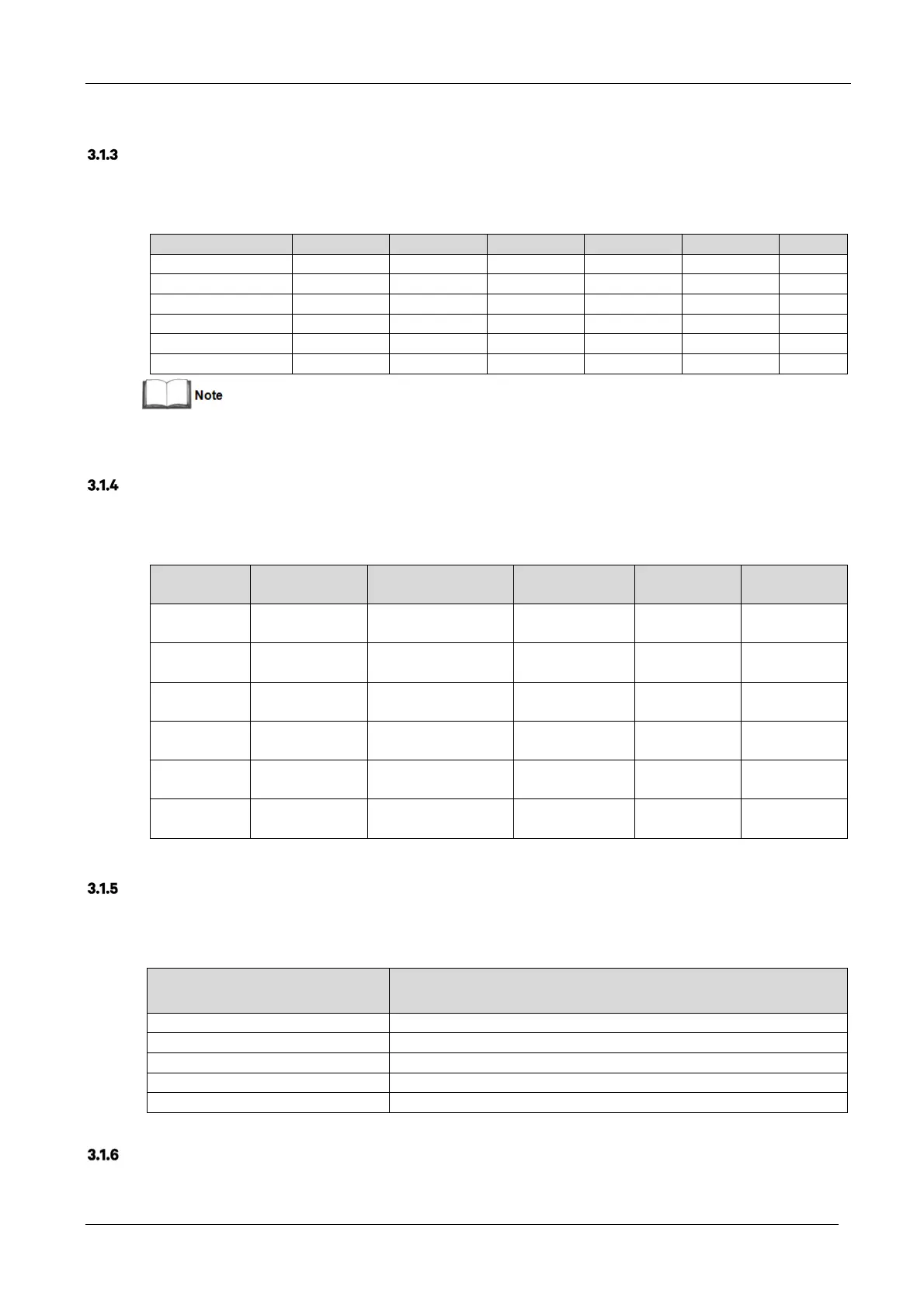
Recommended CSA of UPS Cables
The recommended CSA of the UPS cables is listed in Table 3-2.
Table 3-2 Recommended CSA of the UPS cable (unit: mm
2
, ambient temperature: 25°C)
Model Input Output Bypass Neutral line Earth cable Battery
10 (3-in 3-out ) 10 10 10 10 10 10
10 (3-in 1-out ) 10 10 10 10 10 10
15 (3-in 3-out ) 10 10 10 10 10 10
15 (3-in 1-out ) 10 16 16 16 16 10
20 (3-in 3-out ) 10 10 10 10 10 16
20 (3-in 1-out ) 10 25 25 25 25 16
When the system is in common input configuration and in 3-in 1-out mode, because phase A powers the load, the input cable of
phase A must be selected according to Table 3-2. Input cables of phase B and phase C may refer to Table 3-2.
Selecting the UPS I/O Switch
Table 3-3 indicates the recommended UPS I/O switch capacity, the user may select it as required.
Table 3-3 Selecting the UPS I/O switch
Model Input port External input switch
Circuit breaker
Output port
External
output switch
10
(3-in 3-out )
Terminal block 32A (3P) 50A Terminal block 25A (3P)
10
(3-in 1-out )
Terminal block 32A (3P) 50A Terminal block 63A (1P)
15
(3-in 3-out )
Terminal block 50A (3P) 63A Terminal block 32A (3P)
15
(3-in 1-out )
Terminal block 50A (3P) 63A Terminal block 80A (1P)
20
(3-in 3-out )
Terminal block 63A (3P) 80A Terminal block 50A (3P)
20
(3-in 1-out )
Terminal block 125A (3P) 80A Terminal block 125A (1P)
Distance Between the UPS Connection Point and the Floor
See Table 3-4 for details.
Table 3-4 Min. distance between UPS connection point and floor
UPS connection point
Min. distance(mm)
Rectifier input 1000
Bypass input 1000
AC Output 1100
Battery 1100
PE terminal 1100
Notes
The following points are provided for general guidance only. If there are corresponding local regulations, such
regulations shall prevail.