EXS
User Manual 10H52260UM60 - Rev. 1 - 10/2017 35
Chapter 4 Operator Control and Display Panel
This chapter introduces the functions and use of the components on the UPS operator and display panel, and
provides LCD display information, including the LCD screen types, detailed menu messages, prompt windows
message and UPS alarm list.
4.1 Introduction
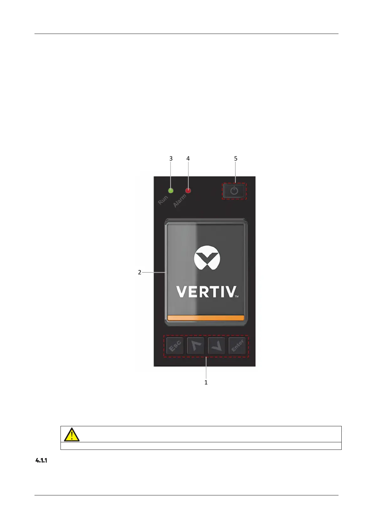
The operator and display panel is located on the front panel of the UPS. The operator and display panel allows the
user operate and monitor the UPS, and view the UPS parameters, Ups and battery status information and any alarm
messages.
As shown in Figure 4-1, the operator and display panel includes an LCD screen, menu keys, and LED indicators (run
indicator and alarm indicator).
1. Menu keys 2. LCD 3. Run indicator
4. Alarm indicator 5. Power button
Figure 4-1 Operation and display panel
Note
The device includes a gravity sensor function, so that the LCD display direction will adapt to the device layout mode.
LED Indicators
T
he LED indicators consist of the run indicator and alarm indicator. Table 4-1 provides a description of these
indicators.