EXS
30 User Manual 10H52260UM60 - Rev. 1 - 10/2017
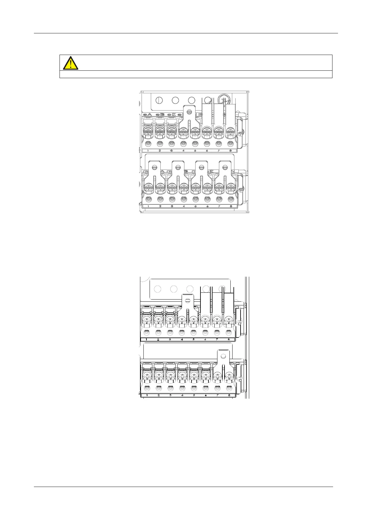
Note
Note that the common input copper shorting bars are fitted before delivery.
Figure 3-4 3-in 3-out, common input configuration cable connection (factory default)
2. 3-in 3-out, split bypass configuration
R
efer to Figure 3-5, remove the three copper shorting bars between the rectifier input terminals (mA-mB-mC) and
the bypass input terminals (bA-bB-bC). Connect the rectifier input cables to the rectifier input terminals (mA-mB-
mC) in the cabinet, and connect the bypass input cables to the bypass input terminals (bA-bB-bC) in the cabinet.
Connect the input neutral line to the terminal N in the cabinet. Make sure that the phase rotation is correct.
Figure 3-5 3-in 3-out, split bypass configuration cable connection
3. 3-in 1-out, common input configuration
Fo
r more details, refer to 8.2.7 .
4. 3
-in 1-out, split bypass configurat
ion
Fo
r more details, refer to 8.2.7 .
Connecting the system output
In the case of 3-in 3-out configurations, connect the system output cables between the output terminals (oA-oB-oC-
oN) and the load; whereas, in the case of 3-in 1-out configurations, connect the system output cables between the