TOTAL WATTS (REAL POWER) TOTAL VA (APPARENT POWER) TOTAL KWH
The totalof Watts shown in sec- tions 1-6 The totalof VA shown in sections 1-6 The total kWh shown in sections 1-6
Table C.4 Totals
NOTE: The tables above are an outline of data that is present in the database .csv file as is not
representative of the actual format of the .csv file. Data stored will vary based on product
configuration.
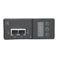
Appendix D: Available Sensors
D.1 Remote sensors
• SRT: Stainless Remote Temperature
• GTHD: Temperature/Humidity/Dew Point
• GT3HD: Temperature/Humidity/Dew Point with two SRT sensors
• RTAFHD3: Temperature/Air Flow/Humidity/Dew Point
• A2D: Converts analog I/O Sensors to Remote Digital Sensors
D.2 Analog I/O sensors
• FS-15: Flood (Water) Sensor
• PFS-100 US / PFS-100 UN: Power Failure Sensor
• RPDS: Door Switch Kit
D.3 Connecting remote sensors
Up to sixteen plug-and-play remote sensors can be attached to the unit at any time via the RJ-12
connectors on the front of the unit. In some cases splitters may be required to add additional sensors.
Each sensor has a unique serial number and is automatically discovered and added to the web page. The
display order of the sensors on the web, is determined by the serial number of each sensor. You can
customize names of each sensor on the Sensors Overview page.
NOTE: Sensors use cat 5, CMP wire and RJ-12 connectors. Wiring must be straight-through. Reverse
polarity temporarily disables all of the sensors until corrected. Sensors use a serial communication
protocol and are subject to network signaling constraints dependent on shielding, environmental noise
and length of wire. Typical installations allow runs of up to 600 feet of sensor wire.
Vertiv | Intelligent Rack PDU Installer/User Guide
72
 Loading...