Vertiv | Liebert® DM | User Manual 24
Mechanical Installation
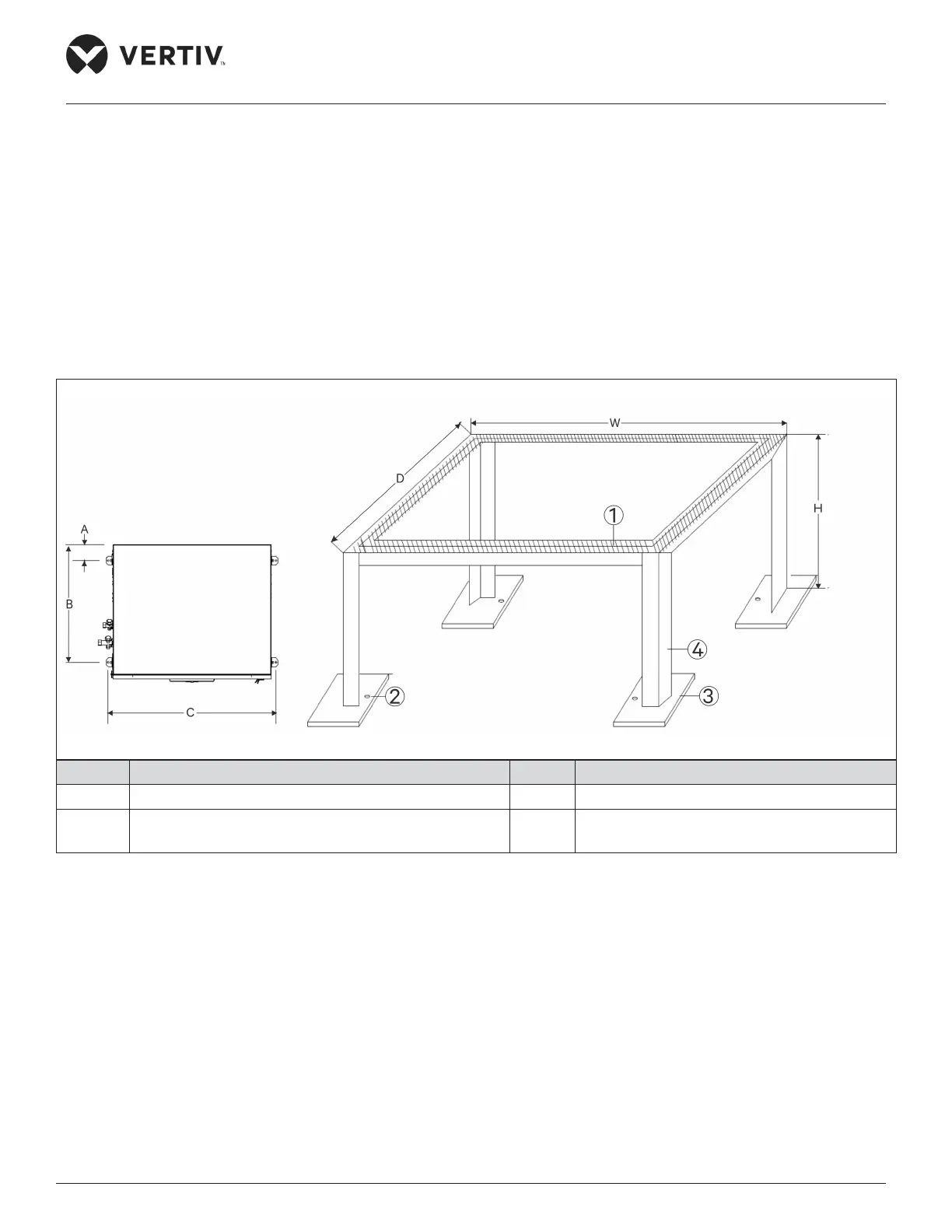
2.5.3. Installation Procedure
1. The floor stand has to be prepared by the installation team according to the dimensions, weight, and height of the unit.
To ensure the rigidness of the structure, size the floor stand according to Figure 2-10 and Table 2-3.
2. According to the position of the fixing hole of the indoor unit, the sheet metal is welded and fixed on both sides of the
beam of the floor stand.
3. Place a layer of wale pad or anti-vibration with 8 mm to 10 mm thickness on the top side of the floor stand, and on the
bottom of the steel plate respectively to avoid transmission of vibration during operation of the unit, as shown in
Figure 2-10.
4. Next, place the indoor unit on the floor stand and fix it with nuts, spring washers, flat washers and bolts (M10).
5. For the upflow unit, swing the grilles up or down to adjust the airflow direction of the indoor unit. The adjustment angle is
45°, as shown in Figure 2-11.
No. Description No. Description
1 Wale pad or anti-vibration (8mm to 10 mm thickness) 3 Steel plate (60x60x4)
2 Fixing hole for expansion bolt (M6x50) 4
Angle iron (30x30x3) or square tube
(25x25x3)
Figure 2-10 Indoor Unit Mounting Hole Position and Base Size (unit: mm)
Top View of Unit
 Loading...


