Vertiv | Liebert® DM | User Manual 25
Mechanical Installation
Table 2-3 Indoor Unit Mounting Hole Position and Base Size
Model A (mm) B (mm) C (mm) W (mm) D (mm) H (mm)
DME07M**UA1 55 276 560 510 385 ≥150
DME12M**UA1 38 403 650 600 500 ≥150
DME17M*0UA1 75 500 800 750 650 ≥150
DME22M*0UA1
90 670 850 800 765
≥150
DME22M*0FA1 ≥450
DME27M*1UA1
90 740 900 850 835
≥150
DME27M*1FA1 ≥450
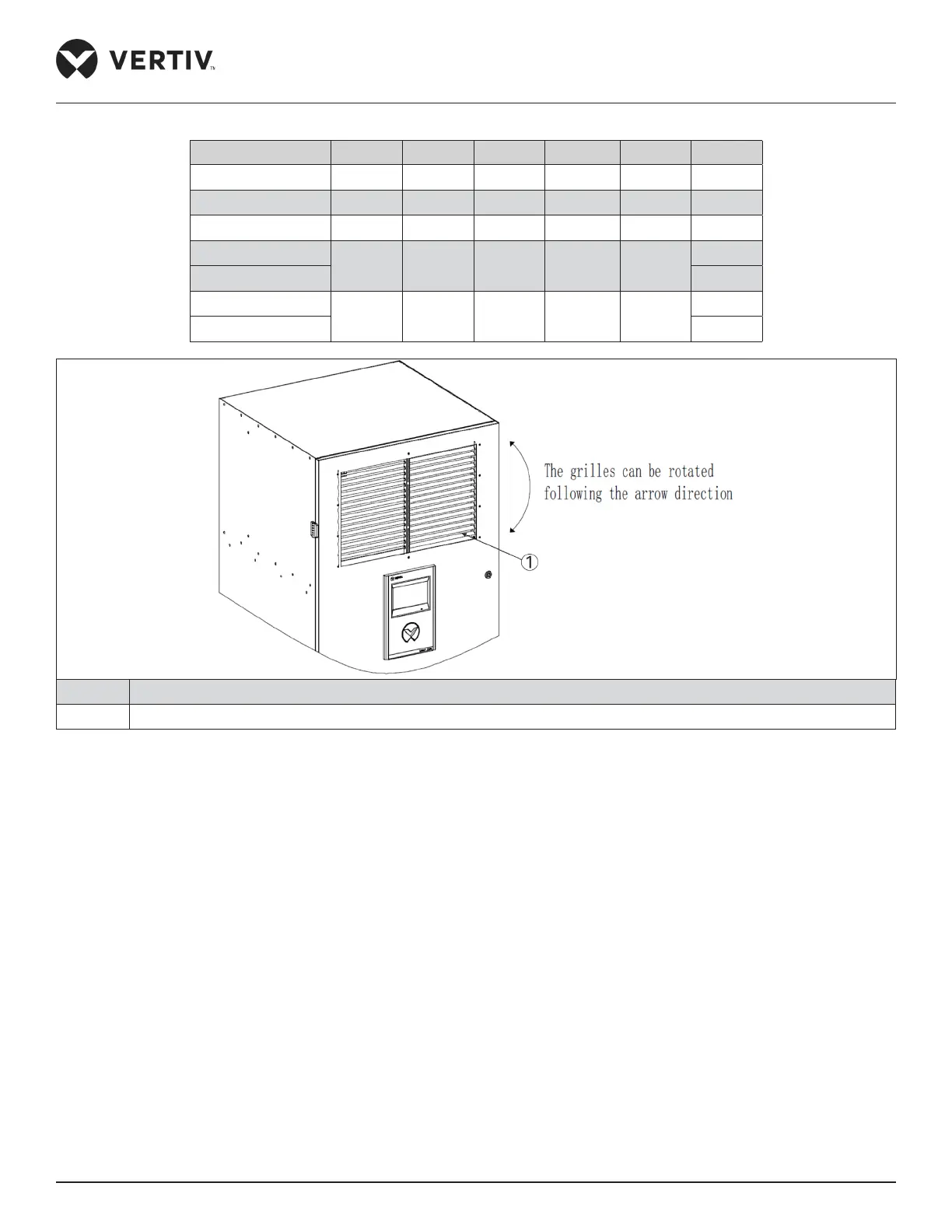
No. Description
1 Grille
Figure 2-11 Changing Airflow Direction
2.6. Installing Outdoor Unit
2.6.1. Installation Notes
• Install the outdoor unit for better security and maintenance accessibility. Do not install it on ground-level sites where
public can access it easily.
• The outdoor unit should be installed away from the residential area. Do not locate it directly in the environment that
requires low noise.
• To ensure the cooling performance of the unit, install the outdoor unit in the outdoor with suicient airflow. Do not install
where dust or snow can obstruct the condensing coil.
• Ensure that there are no steam around the unit, waste heat, and so on. Keep a clearance of more than 450 mm
between the outdoor unit and the wall or obstruct or adjacent devices.
• Prepare a strong solid base capable of supporting the outdoor unit weight (see Table 2-2). The base should be at least 50
mm higher than the installation floor and 50 mm more than the dimensions of the outdoor unit base, as shown
in Figure 2-14.
 Loading...


