Vertiv™ | Liebert® DM | User Manual 59
Electrical Installation
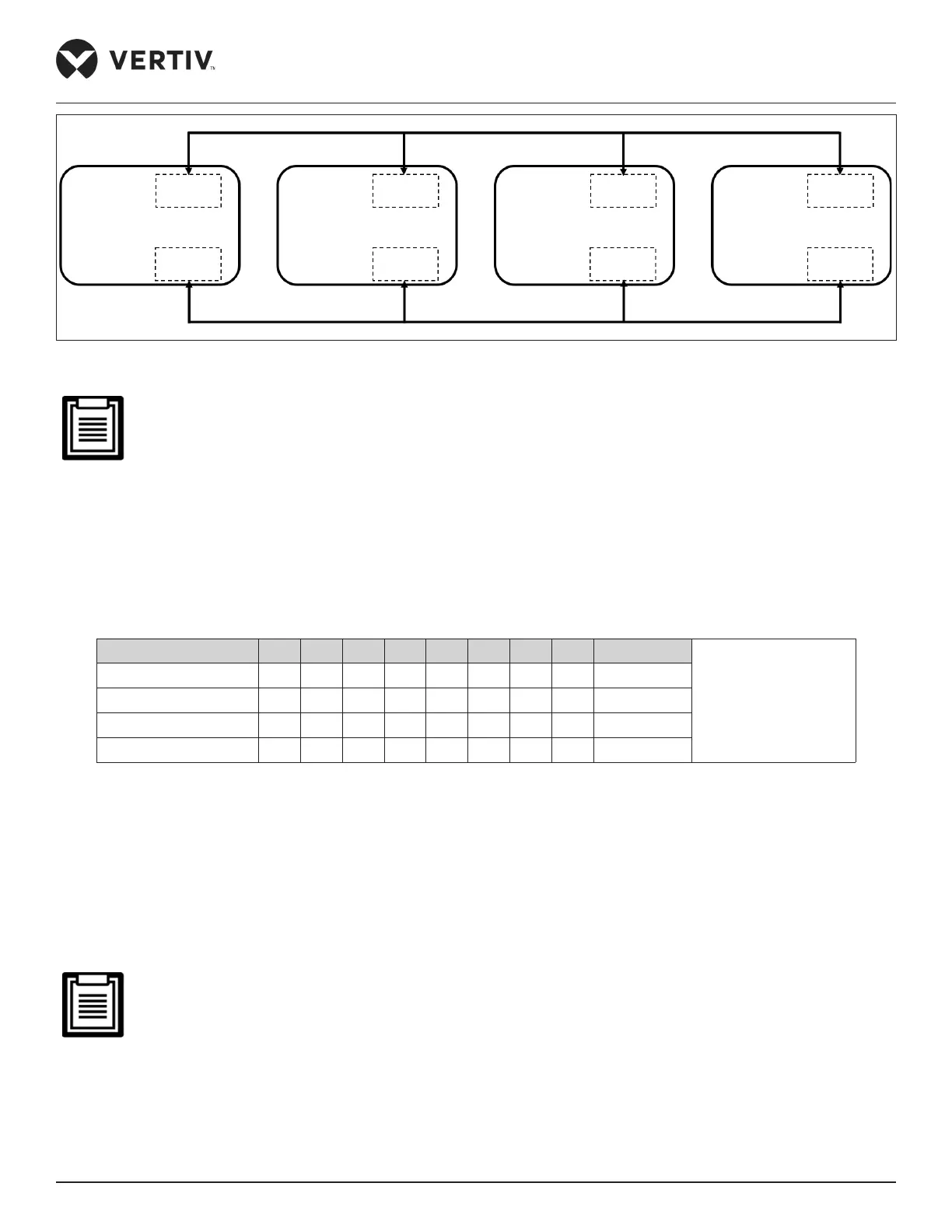
Figure 3-13 Connection Diagram of Teamwork Control Terminal (17/22/27 kW)
1. The first and last teamwork control units need to keep the J27 group control jumper cap on the printed
board (the main unit 1 and the main unit 4 as shown in Figure 3-12). The middle teamwork control unit
needs to remove the J27 teamwork control jumper cap (as shown in the Figure 3-12 that shows main unit 2,
main unit 3).
2. The specific locations of the J27 teamwork control jumper and the SW3 teamwork control DIP switch
address are shown in Figure 3-10. The specific positions of the teamwork control terminals 73 and 74 are
shown in Figure 3-11.
3. If the teamwork control wiring is incorrect and the DIP switch address is incorrect, the group control
function will not function properly.
Table 3-2 Teamwork Control Unit SW3 DIP Switch Address Setting
Unit 1 2 3 4 5 6 7 8 ID No.
ON — “0”
Default ID: 00
Main Unit 1 0 0 0 0 0 0 0 0 00
Main Unit 2 1 0 0 0 0 0 0 0 01
Main Unit 3 0 1 0 0 0 0 0 0 02
Main Unit 4 1 1 0 0 0 0 0 0 03
3.5.2. The Outdoor Unit Signal Cable Connection (for 22 kW/27 kW)
Refer the following procedure to connect the signal cables of the unit:
1. The signal cable diameter of the outdoor unit must not be less than 20 AWG (0.5 mm
2
).
2. Connect one end of the outdoor unit signal cable to the control terminals 70 and 71 on the indoor unit terminal block
shown in Figure 3-11, and the other end to the J6 on the outdoor fan speed controller shown in
Figure 6-1.
3. The dry contact leads to the terminals 70A and 71A.
If the outdoor unit signal cable is not connected properly, the outdoor fan cannot operate normally.
3.5.3. Connecting the Monitoring Interface Cable
The RS485 monitoring interface of the Liebert® DM indoor unit is located on the J14 terminal on the printed circuit board
as shown in Figure 3-10. The monitoring interface is shown in Figure 3-9. The twisted-pair communication cable is used to
connect to the host computer.
Main Unit1 Terminal 74
SW3 switch address 00
J27 Terminal 73
Main Unit2 Terminal 74
SW3 switch address 01
J27 Terminal 73
Main Unit3 Terminal 74
SW3 switch address 02
J27 Terminal 73
Main Unit4 Terminal 74
SW3 switch address 03
J27 Terminal 73
 Loading...


