Vertiv™ | Liebert® DM | User Manual 57
Electrical Installation
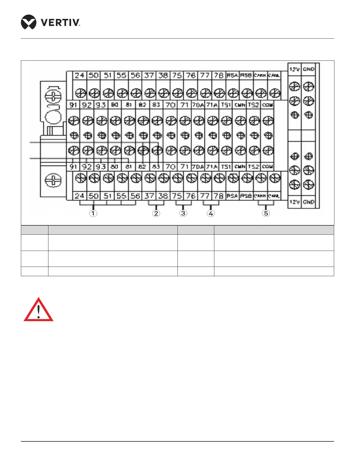
The control terminals on the terminal block are shown in Figure 3-11. The upper part of the terminal block is connected to
the unit, and the lower part is the user control signal line interface.
No. Description No. Description
1
Customized alarm terminal/ water under floor
sensor
4 RS-485 interface
2
37/38 are short connection remove this short
wire at remote shutdown
5 CANH/CANL terminal
3 External general alarm
Figure 3-11 Terminal Block Control Terminal Diagram
The connection personnel must take anti-static measures before connecting the control cables
• SPD (custom 1 terminal)
If the power SPD is configured in the unit, the PIN1 and PIN2 of the customer 1 terminal J19 have been connected with its
alarm signal in factory and alarm is set to be normally closed (NC).
• Remote On/O (custom 2 terminal)
The remote On/O terminal (07 kW/12 kW J19 pin5 pin6, 17 kW/22 kW/27 kW pin37 pin38) can be used to remotely control
the unit ON/OFF status and to stop the unit operation upon special moment. If the inputs of remote On/O terminals are
shorted and the unit power supply is switched On, then unit outputs are normal.
 Loading...


