Vertiv | Liebert® DM | User Manual 17
Mechanical Installation
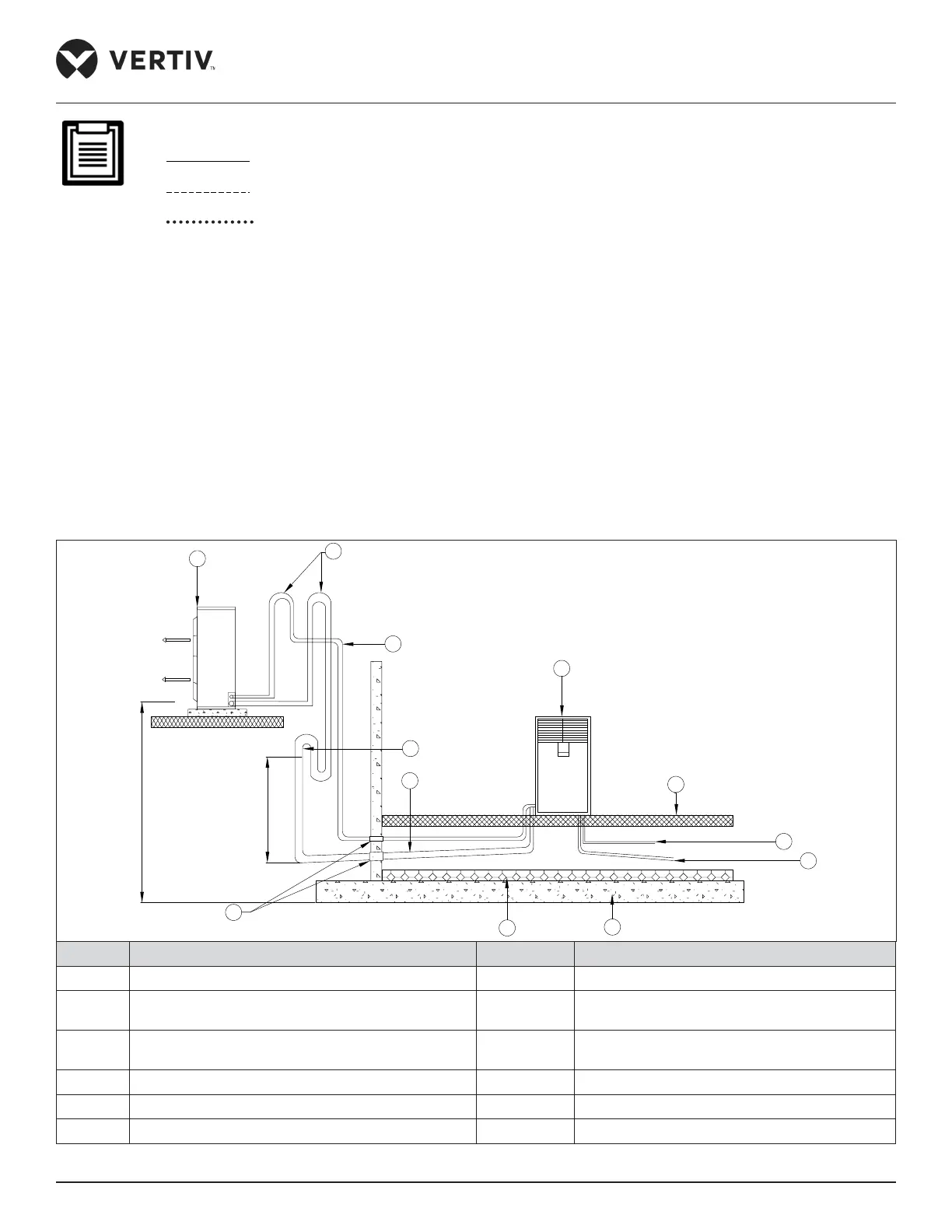
The following points should be considered before checking out the overall layout diagram:
• : Factory piping
• : Field piping (by technical personnel)
• : Represents the link between Suction Temperature Sensor and Thermal Expansion Valve
(TXV).
• The single system is used as an example.
• Components (marked with *) are not supplied by Vertiv but are recommended for the proper circuit
operation and maintenance.
• Components (marked with
#
) is only available for Vertiv™ Liebert® DM 22 kW and DM 27 kW units; and the
Liebert DM 07 kW, DM 12 kW, and DM 17 kW Units are not equipped with sight glass.
• Additional components (marked with +) are required when the equivalent length exceeds 30 m.
2.3.2. System Installation Mode
Ensure that the Liebert DM 07 kW/12 kW /17 kW indoor and outdoor units must be installed vertically, and the indoor unit of
Liebert DM 22 kW/27 kW must be installed vertically, while the outdoor unit of Liebert DM 22 kW/27 kW can be installed
horizontally or vertically. The system installation schematic diagram explains the process of installation of the outdoor unit.
20m
7.5m
1
3
4
5
6
7
8
9
10
12
11
No. Description No. Description
1 Outdoor Unit 7 Heat insulation material
2
Back bend (must be higher than the highest copper pipe
of the condenser)
8 Floor
3
Liquid line
(avoid exposure to direct sunlight)
9
Condensate water drain pipe
(to outdoor, slope 1:200)
4 Trap 10 Humidifier water supply pipe (to water tap)
5 Discharge pipe (slope 1:200) 11 Isolation floor
6 Sealed 12 Indoor Unit
Figure 2-2 Condenser is Placed Higher than the Compressor during Installation
 Loading...


