Vertiv | Liebert® DM | User Manual 18
Mechanical Installation
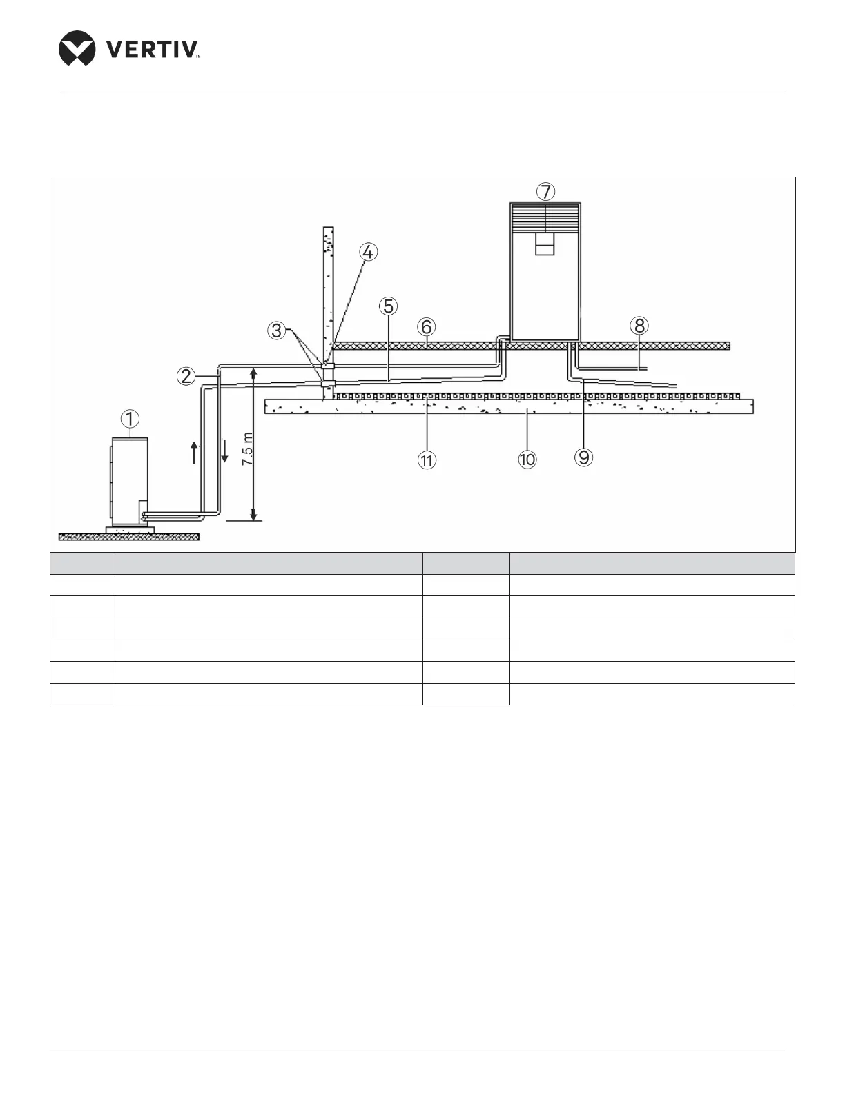
If the outdoor unit is installed higher than the indoor unit (see Figure 2-2), a back-bend should be fitted to the discharge line
and liquid line of the outdoor unit, so as to prevent the liquid refrigerant from flowing back when the outdoor unit stops. The
top end of the inverted back-bend should be installed higher than the ultimate level of the copper pipe of the outdoor unit.
However, if the outdoor unit is installed lower than the indoor unit, then there is no need of modification.
No. Description No. Description
1 Outdoor unit 7 Indoor unit
2 Liquid Pipe (not be exposed to Sun) 8 Humidifier water supply pipe (to water tap)
3 Sealed 9 Condensation water drain pipe (to outdoors)
4 Protection tube 10 Floor
5 Discharge pipe (Slope 1:200) 11 Insulation material
6 Isolation floor
Figure 2-3 The Condenser is Placed Lower than the Compressor during Installation
The illustration in Figure 2-2 depicts the schematic diagram of system installation when the outdoor unit is installed at a
higher level than the indoor unit and Figure 2-3, when the outdoor unit is installed at a lower level than the indoor unit.
 Loading...


