Vertiv™ | Liebert® DM | User Manual 55
Electrical Installation
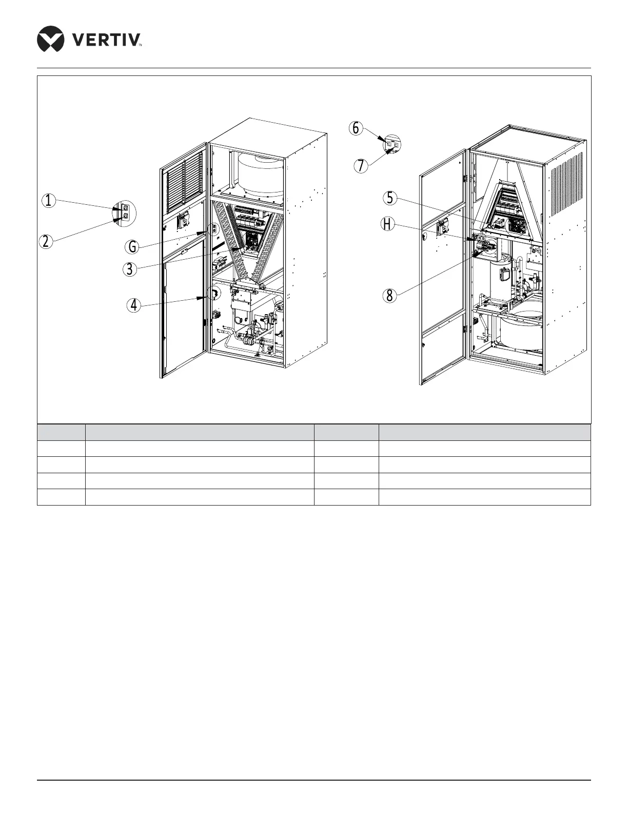
(Amplified View of 'G')
(Amplified View of 'H')
Upflow Unit Downflow Unit
No. Description No. Description
1 Energy-saving card 5 Control terminal
2 RDU-A/SIC 6 Energy-saving card
3 Control terminal on the PCB 7 RDU-A/SIC
4 Control terminal on the terminal block 8 Control terminal on the terminal block
Figure 3-9 Control Terminal Position (22 kW/27 kW)
 Loading...


