Vertiv | Liebert® DM | User Manual 31
Mechanical Installation
Prior to start-up, ensure that all piping connections have been completed and there is no leakage in the
system.
2.6.6. Connecting Refrigerant Piping
• The copper pipes from the factory are available in length of 7.5 m (see Table 2-5). Refer Table 2-9 and Table 2-10 for the
pipe sizes. In case of longer pipe is required contact Vertiv representative.
• Select the appropriate dimension (Pipe diameter & Wall thickness) of refrigerant liquid pipes connecting the outdoor unit
to ensure that the pressure drop of the refrigerant liquid through the pipe during unit operation does not exceed 40 kPa
(5 psi to 6psi).
• The pipe should be installed and removed with care so that they will not get damaged. Use tube benders and make all
bends before connecting refrigerant piping of the indoor and the outdoor units.
• If brazing is required, all refrigerant piping should be connected with silver-brazed joints. The copper pipe is filled with
nitrogen gas during the brazing process to prevent oxidation of the copper piping.
• Prior to use, check piping supports, leakage testing, dehydration of refrigerant pipes and evacuation. Use vibration
isolating support to isolate the refrigeration piping from the building.
• Use a soft and flexible material to pack around the piping to protect them when sealing openings in walls and to reduce
vibration transmission.
• When installing the outdoor unit 7.5 m higher than the indoor unit, the trap should be installed on the discharge pipe (Oil
trap). This trap will retain lubricant oil in the o cycle of the compressor. When the compressor starts, oil in the trap will be
carried up the vertical riser and return to the compressor immediately.
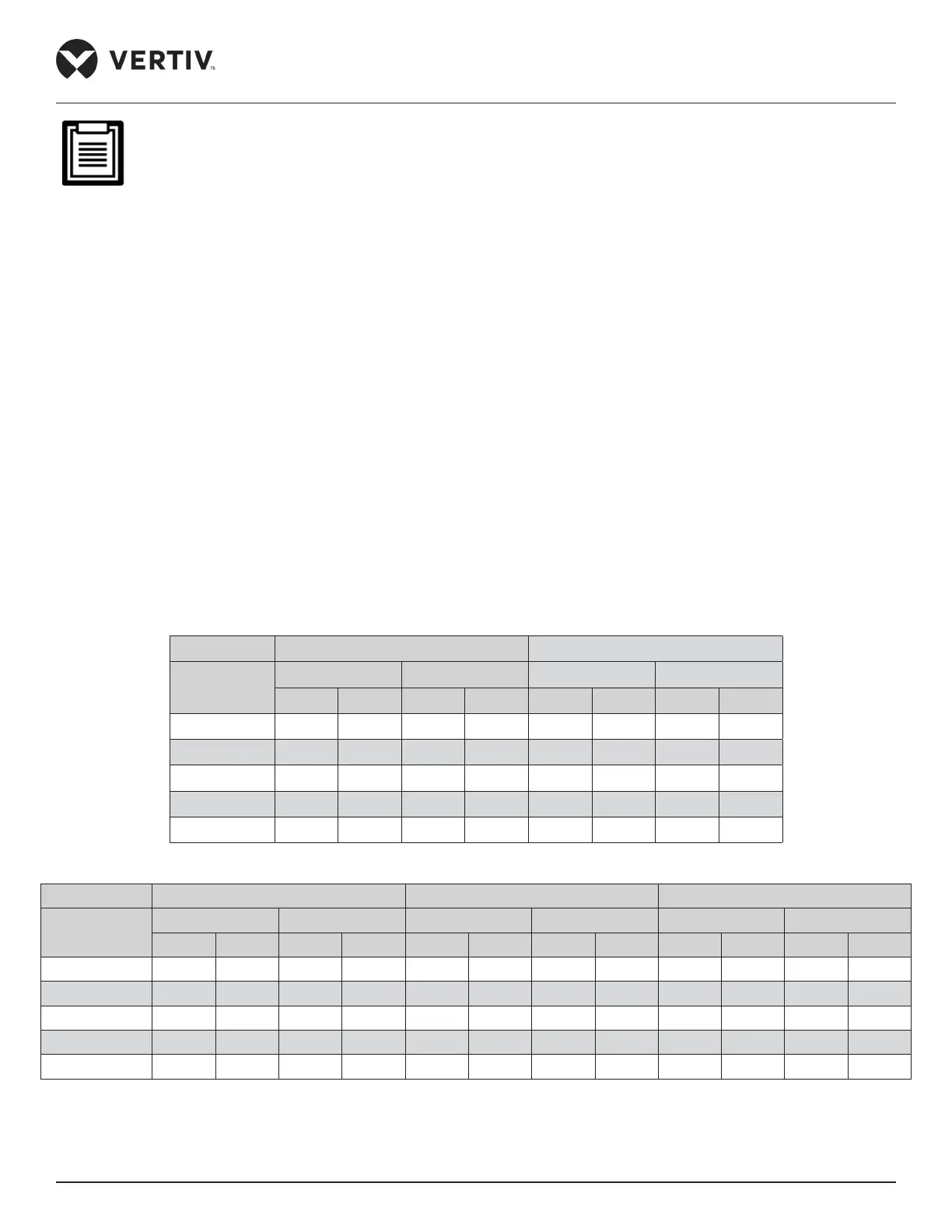
Table 2-9 Recommended Size of the Pipeline
Model DME07 DME12
Pipe Length
(m)
D L D L
mm inch mm inch mm inch mm inch
10 12.7 1/2 9.5 3/8 16.0 5/8 12.7 1/2
20 12.7 1/2 9.5 3/8 16.0 5/8 12.7 1/2
30* 12.7 1/2 9.5 3/8 16.0 5/8 12.7 1/2
40* 12.7 1/2 9.5 3/8 16.0 5/8 12.7 1/2
50* 12.7 1/2 9.5 3/8 16.0 5/8 12.7 1/2
Table 2-10 Recommended Size of the Pipeline
Model DME17 DME 22 DME27
Pipe Length
(m)
D L D L D L
mm inch mm inch mm inch mm inch mm inch mm inch
10 16.0 5/8 12.7 1/2 19.0 3/4 16.0 5/8 19.0 3/4 16.0 5/8
20 19.0 3/4 12.7 1/2 19.0 3/4 16.0 5/8 19.0 3/4 16.0 5/8
30 19.0 3/4 16.0 5/8 19.0 3/4 16.0 5/8 19.0 3/4 16.0 5/8
40* 19.0 3/4 16.0 5/8 19.0 3/4 16.0 5/8 22.0 7/8 16.0 5/8
50* 22.0 7/8 16.0 5/8 22.0 7/8 16.0 5/8 22.0 7/8 19.0 3/4