Vertiv | Liebert® DM | User Manual 86
Outdoor Fan Speed Controller (Only for 22 kW/27 kW)
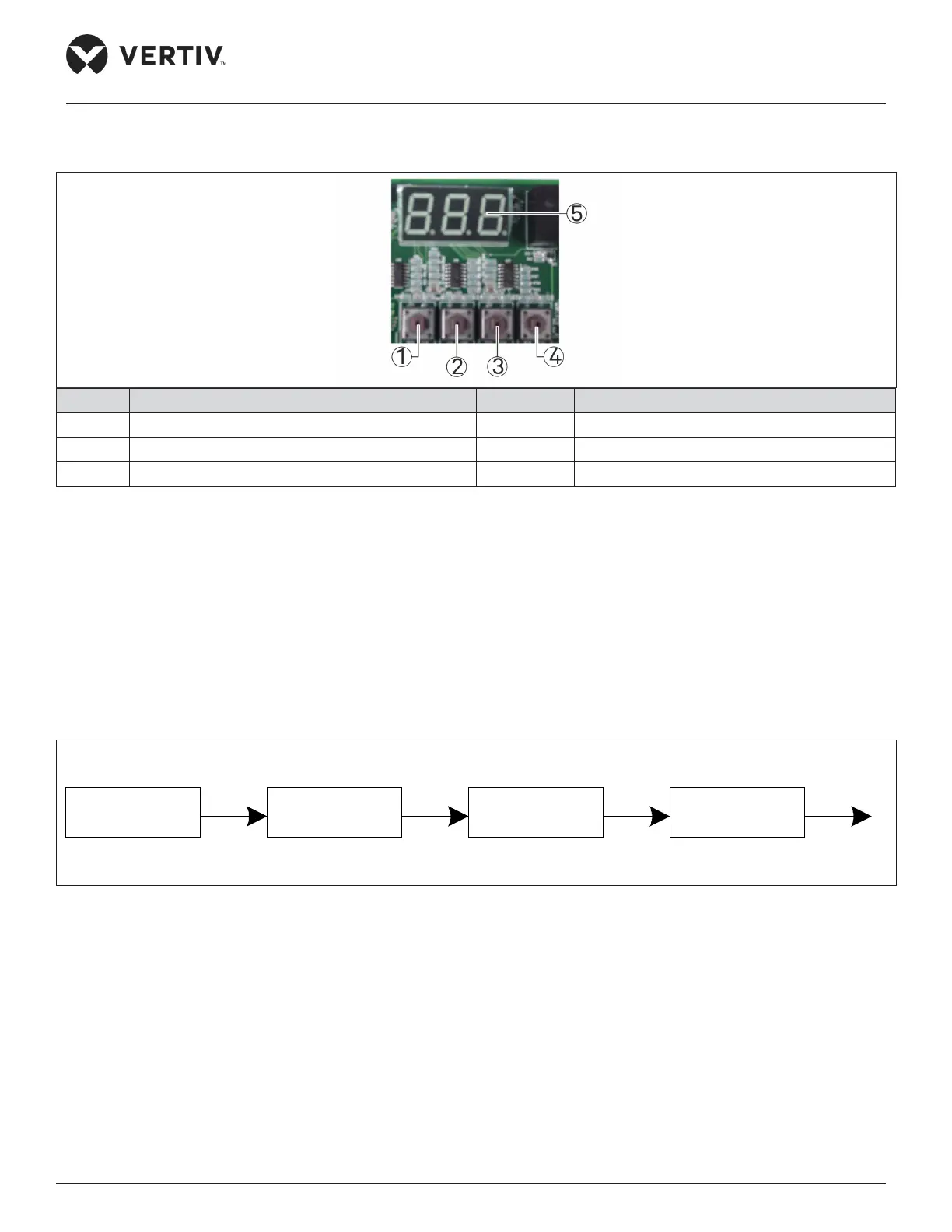
The buttons and the digital tube are located in the upper right corner of the fan speed controller board as shown in Figure
6-1, and its appearance is shown in Figure 6-2.
No. Description No. Description
1 ENT key 4 ESC Key
2 UP key 5 LED
3 Down key
Figure 6-2 Buttons and the Digital Tube
6.3. Human-Machine Interface Operation Instructions
6.3.1. Power-on Initial Interface
When the fan speed controller starts to power on, it displays the maximum value of “F01”, condensing pressure 1 and
condensing pressure 2, where “F01” indicates the maximum pressure. When the pressure sensor is not configured, the short
circuit jumper cap of the current type pressure sensor is not jumped or the pressure sensor fails, the digital tube displays the
pressure value as “88.8”. The display sequence is shown in Figure 6-3 (“16.1” in the figure is an example data, and the specific
value depends on the sampling result).
F01 16.1
F01
16.1
Figure 6-3 Power-on Initial Interface