Vertiv | Liebert® DM | User Manual 40
Mechanical Installation
2.6.9. Humidifier and Water Supply Piping Connection (If Applicable)
A shut-o valve should be installed on this piping for maintenance. The humidifier water supply piping needs to be
connected to the interface reserved on the unit, as shown in Figure 2-18 to Figure 2-22. The unit has a copper pipe with an
outer diameter of 6.35 mm and a 1/4” copper nut and a 1/4” x 1/2” conversion copper threaded connector at the end of
the copper pipe.
• Where the main line pressure may exceed 700 kPa (the main line pressure range should be 100 kPa to
700 kPa), a pressure reducer should be installed.
• Where the main pipeline pressure is lower than 100 kPa, there should be a water-collecting tank and
a water pump system should be installed.
• Some models may contain components, where local regulations need to be considered.
2.7. Removing Transport Fasteners and Shock Absorbers
The fasteners and vibration absorbers are mounted on the unit to protect partial components from getting damaged and
distorted due to bumping, impact, and resonance. Removal of these fasteners and absorbers is necessary before installation
and commissioning the unit.
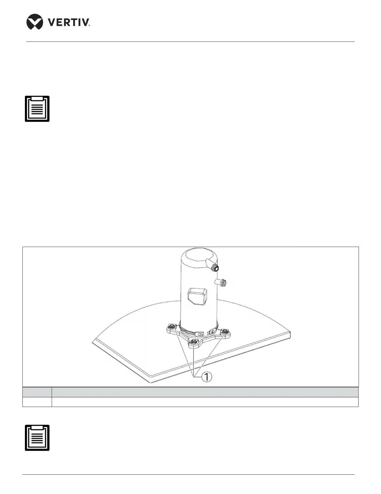
• Remove the transport fastening sheet metal of the compressor
In order to absorb the vibration of the compressor operation and reduce the vibration noise, a vibration isolator is installed on
the compressor foot. However, this damping technology does not suppress compressor shaking well during transportation,
which may cause loose connections or wear of components. In order to eliminate this possible problem while transporting,
the “U” type sheet metal for transportation fixing plate is installed on the three fixed feet of the compressor,
as shown in Figure 2-26.
No. Description
1 Fixing plates (3 pcs)
Figure 2-26 Fastening Sheet Metal for Compressor
• Remove the “U“ type fixing plates after installation, and then restore the bolts and washers in reverse
sequence of the assembly process.
• The fastening torque of the bolts is (12±1) Nm.