Vertiv | Liebert® DM | User Manual 37
Mechanical Installation
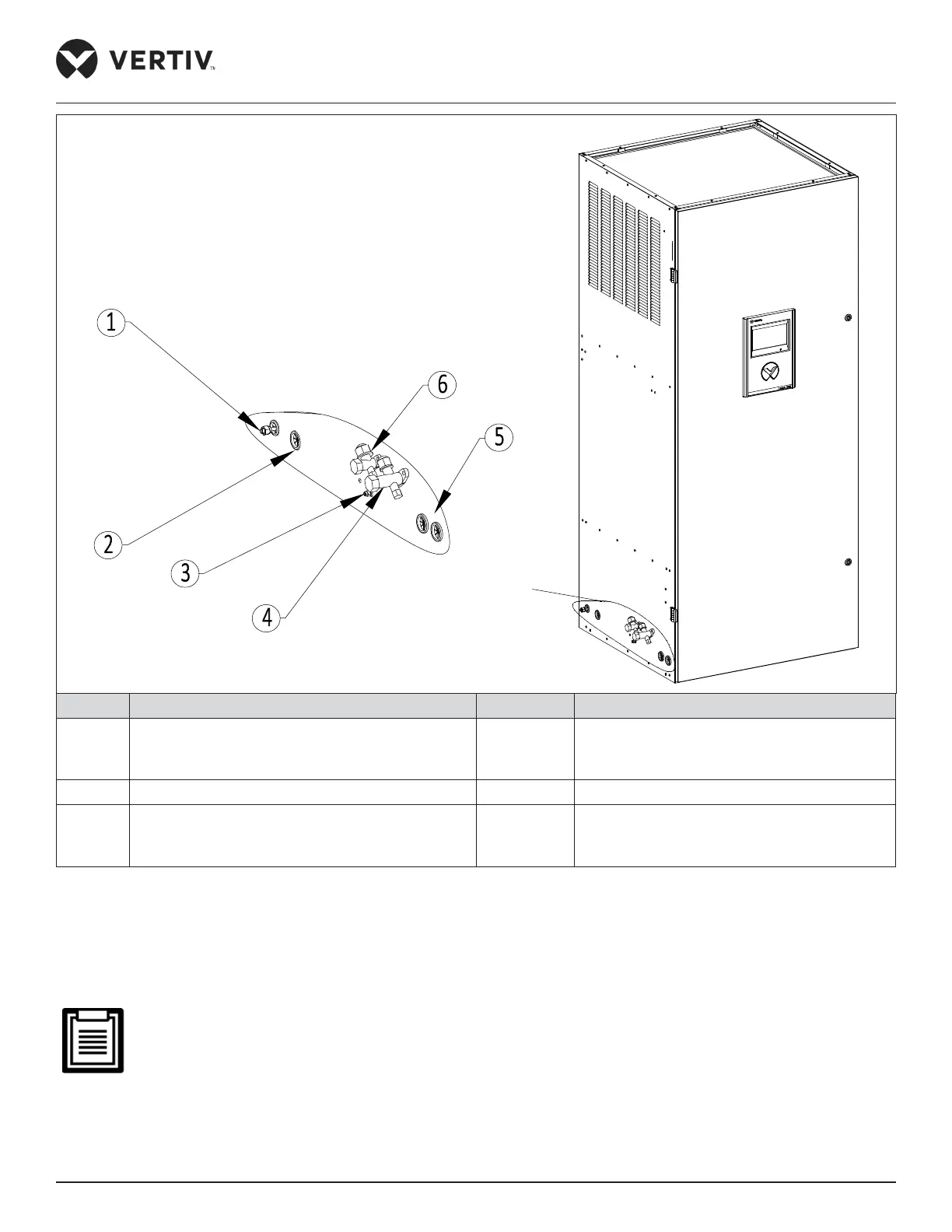
No. Description No. Description
1 Humidifier inlet pipe (1/4” BSP, 1/2” BSP Male) 4
Discharge line shut o service angle valve
(3/4”-19 mm straight pipe, 1-1/16”- 14 UNF
Connector thread)
2 Condensate drain pipe (OD 22 mm) 5 Cable hole (ID 29 mm)
3 Schrader Valve 6
Liquid line shut o service angle valve (5/8”-
16 mm straight pipe, 7/8”- 14 UNF Connector
thread)
Figure 2-22 Pipeline Connector Interface (DME22 and DME27 Downflow Unit)
• Connecting discharge pipe
Connect one end of the discharge pipe to the discharge line shut o service angle valve of the indoor unit shown in
Figure 2-18 to Figure 2-22, and the other end to the discharge line shut o service angle valve of the outdoor unit shown in
Figure 2-23 to Figure 2-25.
Horizontal sections of the discharge pipe should be sloped down from the compressor with a slope of at least
1:200 (5 mm down for each 1 m run). The discharge pipes should be insulated where they are routed in the
conditioned space (including under a raised floor).
A
B