Installation drawings
C --- 4Liebert HPM --- A/W/F/D/H
English
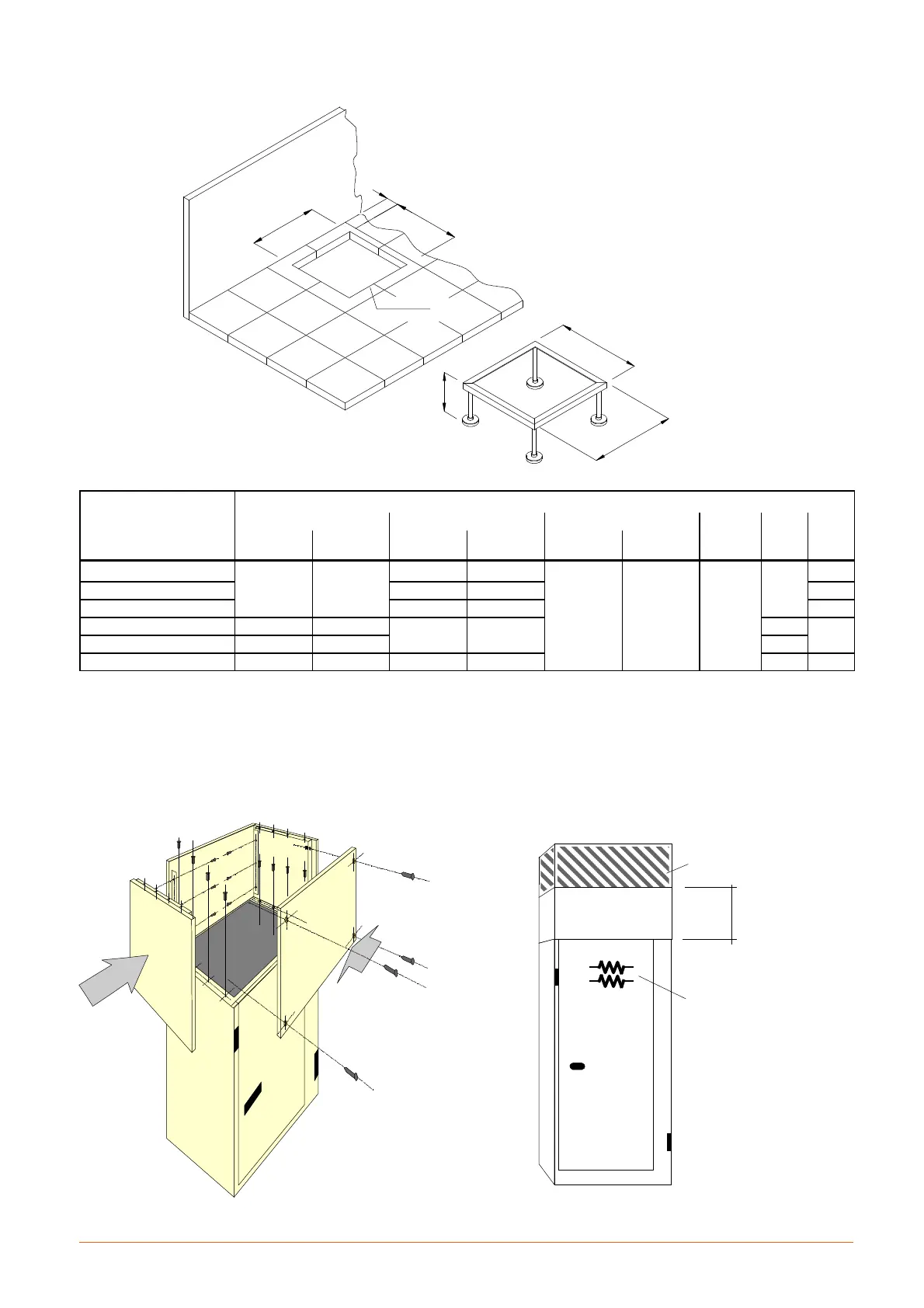
Fig. 6 --- Hole in raised floor
D
A
C
B
E
F
BASE FRAME
ACCESSORY
FRONT UNIT
FRONT
UNIT
WALL
MODELS
Dimensions (mm)
A B C
D E F
without base
frame
with base
frame
without base
frame
with base
frame
without base
frame
with base
frame
S0F
690 750
320 390
50 10
± 300
± 500
± 800
740
380
S 0 H --- 1 A --- 1 D 420 490 480
S 1 E --- 1 G --- 2 E --- 2 G 670 740 730
M 2 H --- 3 A
930 1000
770 840
990
830
M3F ... 7L
1680 1750 1740
L 8 F --- 9 H
2460 2550 805 895 2550 885
CAUTION: For ”UNDER” units installed on raised floor, inhibit inappropriate access to the unit from the base to not---authotized staff: i.e. fixing
the floor panels up to 850 mm from the unit.
F i g . 7 --- E x t e n s i o n h o o d Fig. 8
Over conditioner with electrical heaters.
Upflow ducted conditioner equipped with
electric-al heaters, connected to air duct not
supplied by Vertiv Pay attention to the
position of insulating material!
² 30 cm
Heaters
Insulation
Note: See Chap. 2