Fit the tool for rotating the crankshaft.
Rotate the crankshaft using the tool tted previously until the cyl-
inder concerned is at B.D.C.
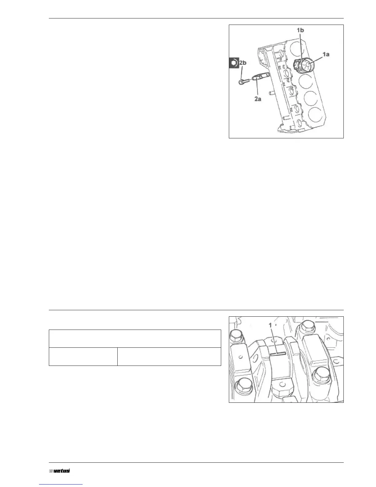
Fit piston-connecting rod assembly (1 a) complete with half-bear-
ing using tool (1b).
The piston-connecting rod assemblies are tted in the cylin-
der block/crankcase so that the combustion chamber in the
piston is facing the intake side.
For the selection of the connecting rod half-bearings, follow
the procedure described previously for the main journal half-
bearings.
Fit connecting rod cap (2 a) complete with half-bearing and se-
cure it without tightening bolts (2b).
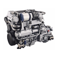
Fit the connecting rods so that the number stamped on each
rod faces toward the same side as the number stamped on the
big end (inlet side).
For the remaining cylinders, carry out the same operations to ret
the pistons and connecting rods.
Test the crankpin clearance by applying plastigage to measure
crankpin installation clearance.
Tighten connecting rod cap bolts to the recommended torque.
Connecting rod big end bearing caps
Bolt M9 (da Nm) 2.4 ÷ 2.6 + 60°