PAGE 9 of 36 VR GSM DOOR INTERCOM TECHNICAL MANUAL VER2.0.0
CODELOCK MODULE (VR4KCLM, 800CL)
The codelock includes three relay outputs (Only 2 on the 800CL), two push to exit button
inputs and operates from a 12-24V ac/dc power supply. Up to 2 unique codes can be
programmed, each in the range of 4-8 digits. Relay time can be programmed from 01 – 99
seconds or set to latching mode with a relay time of 00 (To latch, type in the code followed
by Enter, to unlatch, type in the code followed by clear).
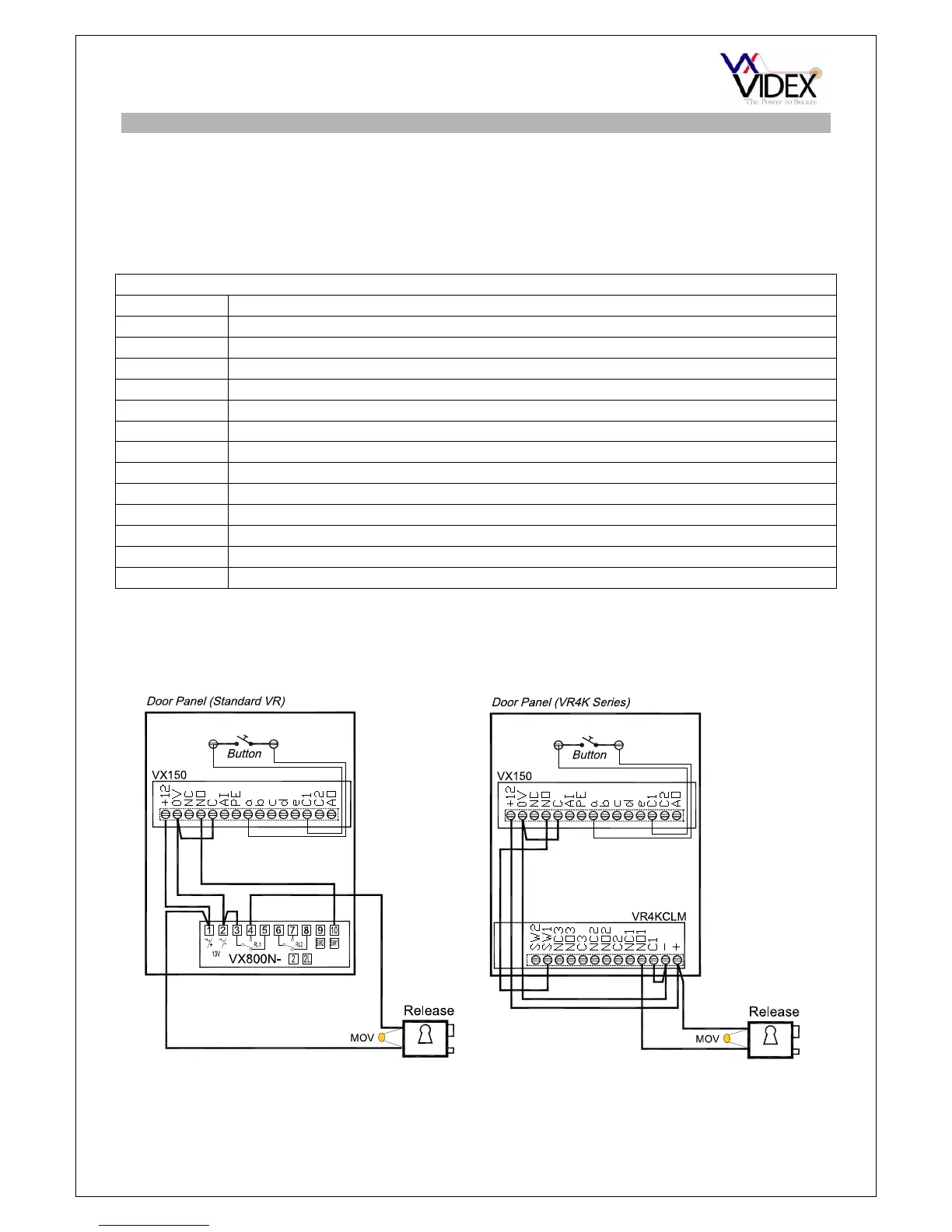
Art.4800 Connections
Connection Function
+ 12-24V ac/dc power input
- 0V power input
C1 Common connection of relay 1 (Dry contact)
NO1 Normally open connection of relay 1 (Dry contact)
NC1 Normally closed connection of relay 1 (Dry contact)
C2 Common connection of relay 2 (Dry contact)
NO2 Normally open connection of relay 2 (Dry contact)
NC2 Normally closed connection of relay 2 (Dry contact)
C3 Common connection of relay 3 (Dry contact)
NO3 Normally open connection of relay 3 (Dry contact)
NC3 Normally closed connection of relay 3 (Dry contact)
SW1 Push to exit input for relay 1 (Triggered by 0V)
SW2 Push to exit input for relay 2 (Triggered by 0V)