21
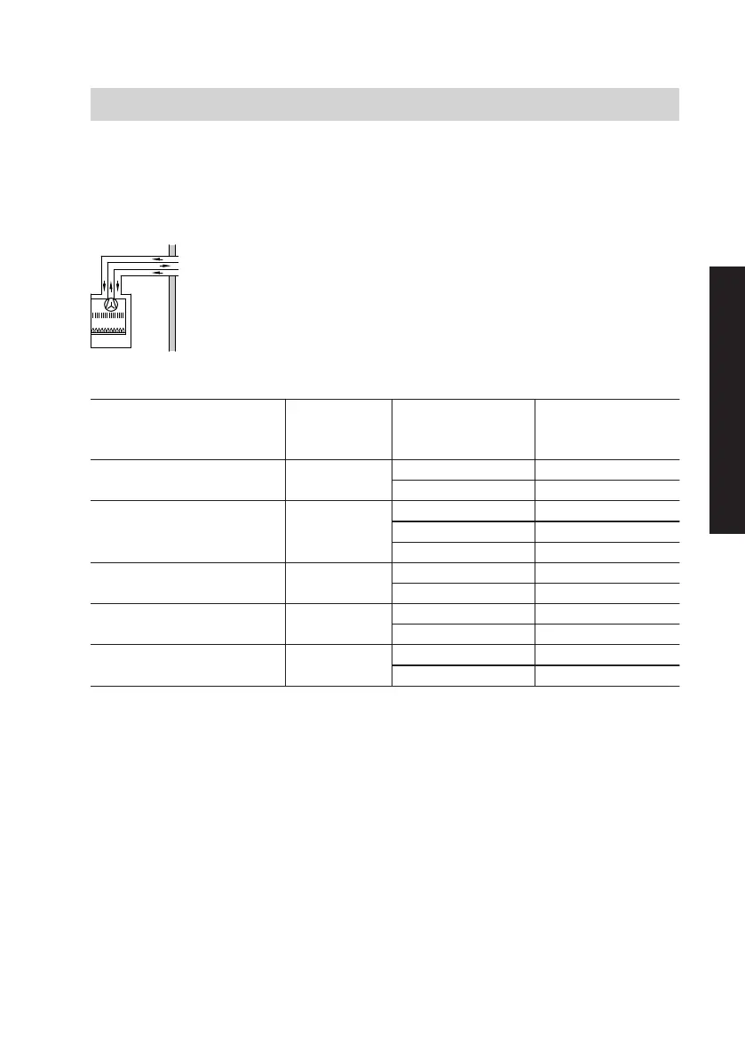
Using a flue restrictor
Routing type external wall connec-
tion
Type (model) C
12x
Rated heating output Balanced
flue system
Length of bal-
anced flue pipe
Flue restrictor
kW
7 mm
m
Internal 7 mm
18 60/100 ≤ 3 41
> 3 ≤ 5 44
22 60/100 ≤ 1 41
> 1 ≤ 3 43
> 3 ≤ 5 46
24 60/100 ≤ 1 43
> 1 ≤ 5 46
30 60/100 ≤ 1 50
> 1 ≤ 3 –
36 80/125 ≤ 1 –
> 1 ≤ 3 –
Deductions from the max. length of
the balanced flue pipe through the
following components:
■ Balanced flue bend 45°: 0.5 m
■ Balanced flue bend 90°: 1.0 m
■ External wall connection: 1.0 m
Note
■ An inspection piece with a conden-
sate trap should be inserted in the
balanced flue line. Connect the con-
densate trap to the condensate drain.
■ If the balanced flue line is routed
through a metal roof: Fit a seal on the
roof outlet. The balanced flue line
must not come into contact with the
metal roof.
Installation sequence
Mounting the boiler and making the connections
(cont.)
5837146
Installation
 Loading...