Reduced internal shaft dimensions
System size A
External diameter;
female connection
Reduced internal shaft dimension
a b c
square or rectangular
(short side)
round
Ø mm mm Ø mm
80 94 120 135
100 128 150 165
Minimum dimension of shafts in which a flue may be used (positive
pressure operation) without separate calculation.
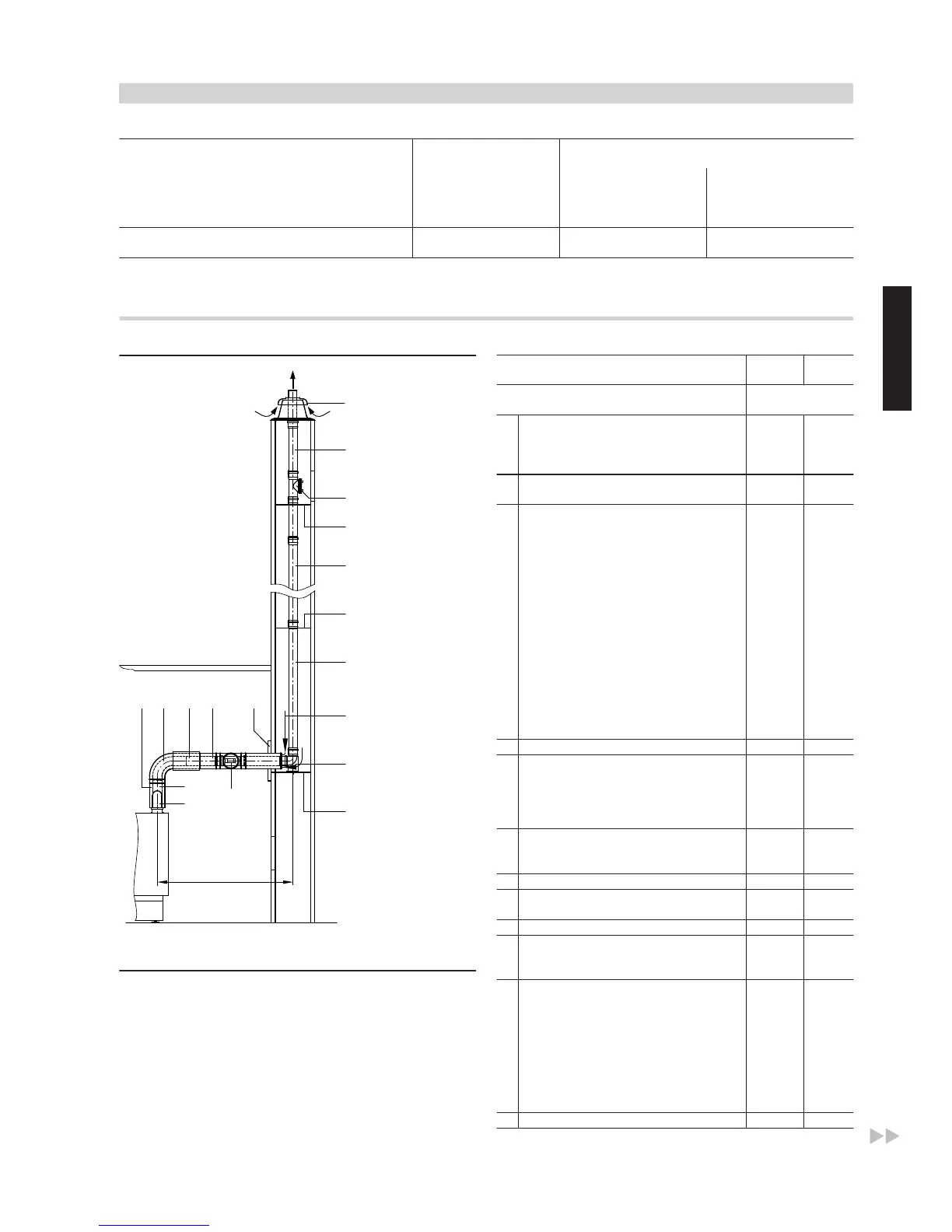
Flue, system size 80 and 100 (components) (type C
63x
to TRÖI 2009)
Illustration with the Vitoladens 300-C
A
Ventilation air
B
Flue gas
C
Inspection port
D
Connection piece
Rated heating output (kW) up to
35.4
from
42.8
System size
Ø mm
1
Boiler flue connection
For balanced flue operation and coaxial
balanced flue routing
(Part of the standard boiler delivery)
80/125 100/150
Balanced flue pipe
With test ports (160 mm long)
80/125 100/150
2
Standard shaft pack (PPs, rigid)
Comprising:
– Support bend
– Support rail
– Shaft cover (PPs)
– Spacers (5 pce, max. clearance 5 m)
or
80 100
Standard shaft pack (metal/PPs, rigid)
For twin flue chimneys; one flue for solid
fuel boilers
Comprising:
– Support bend
– Support rail
– Shaft cover (metal)
– Terminal pipe (stainless steel)
– Spacers (5 pce, max. clearance 5 m)
80 100
Spacers (3 pce, max. clearance 5 m) 80 100
3
Pipe 80 100
1.95 m long (2 pce = 3.9 mm)
1.95 m long (1 pce)
1 m long (1 pce)
0.5 m long (1 pce)
Bend (for use in corbelled chimneys)
30º (2 pce)
15º (2 pce)
80 100
4
Inspection piece, straight (1 pce) 80 100
5
Balanced flue inspection piece, straight
(1 pce)
80/125 100/150
6
Wall bezel 125 150
7
Balanced flue pipe
1 m long
0.5 m long
80/125 100/150
8
Balanced flue bend
87º (1 pce)
45º (2 pce)
or
80/125 100/150
Balanced flue inspection bend 87º
(1 pce)
or
80/125 —
Balanced flue inspection tee 87º
(1 pce)
— 100/150
9
Balanced flue slide coupling 80/125 100/150
Design and sizing information for the Vitoladens 300-C, -T, and Vitorondens 200-T, 222-F
(cont.)
VITOLADENS, VITORONDENS
VIESMANN
11
5822 452 GB
2

 Loading...