A
Flue gas
B
Ventilation air
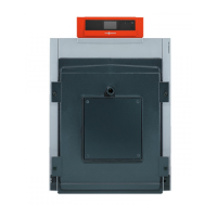
Separate ventilation air and flue gas routing
(type C
83x
, to TRÖl 2009)
The boiler draws combustion air from outside via a separate supply
pipe routed through the external wall, and expels flue gas to the atmos-
phere via a shaft leading through the roof.
The connection piece to the chimney is designed as a coaxial pipe.
This balanced flue system is used if the existing chimney is unsuitable
for routing combustion air due to its dimensions or characteristics
(deposits).
For a detailed description, see page 31.
1.8 Flue installation options for open flue operation
(Separate ventilation air aperture with 150 cm
2
or 2 × 75 cm
2
cross-section required)
Shown with the Vitoladens 300-W.
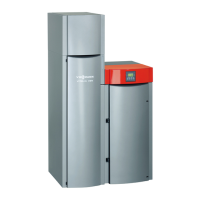
In an installation room (non-living space) with one or more full storeys above
A
Flue gas
B
Secondary ventilation
C
Ventilation air
Routing through a shaft
(type B
23
, to TRÖl 2009)
The boiler draws combustion air from the installation room and expels
flue gas through the flue via the roof (balanced flow).
For a detailed description, see page 34.
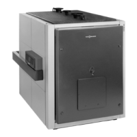
A
Flue gas
B
Secondary ventilation
C
Ventilation air
Connection to a moisture-resistant chimney (MR chimney)
(type B
23
, to TRÖl 2009)
The boiler draws combustion air from the installation room and routes
flue gas through the moisture-resistant chimney via the roof.
For a detailed description, see page 37.
Flue systems
(cont.)
VITOLADENS, VITORONDENS
VIESMANN
9
5822 452 GB
1

 Loading...