Minimum internal shaft dimensions to DIN V 18160
System size A
External diameter;
female connection a
Ø mm
Minimum internal shaft dimension
b c
square or rectangular
(short side)
mm
round
Ø mm
80 94 135 155
80 (flexible) 100 140 160
100 128 170 190
100 (flexible) 125 165 185
Max. number of bends:
■ 87º: 3 pce
or
■ 45º: 3 pce
or
■ 30º: 4 pce
or
■ 15º: 4 pce
The annular gap must be at least 3 cm wide at the shaft inlet.
Flue, system size 80 and 100 (components) (type B
23
to TRÖI 2009)
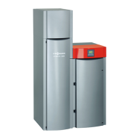
Illustration with the Vitoladens 300-C
A
Ventilation air aperture, min. 150 cm
2
or 2 × 75 cm
2
B
Flue gas
C
Inspection port
D
Connection piece = ¼ of the vertical length or max. 3 m
E
Secondary ventilation
Rated heating output (kW) up to
35.4
from
42.8
System size
Ø mm
1
Boiler flue connection (part of the stand-
ard boiler delivery)
80 100
2
Standard shaft pack (PPs, rigid)
Comprising:
– Support bend
– Support rail
– Shaft cover (PPs)
– Spacers (5 pce, max. clearance 5 m)
or
80 100
Standard shaft pack (metal/PPs, rigid)
For twin flue chimneys; one flue for solid
fuel boilers
Comprising:
– Support bend
– Support rail
– Shaft cover (metal)
– Terminal pipe (stainless steel)
– Spacers (5 pce, max. clearance 5 m)
80 100
Spacers (3 pce, max. clearance 5 m) 80 100
3
Pipe 80 100
1.95 m long (2 pce = 3.9 m)
1.95 m long (1 pce)
1 m long (1 pce)
0.5 m long (1 pce)
4
Inspection piece, straight (1 pce) 80 100
5
Bend
87º (1 pce)
45º (2 pce)
80 100
6
Ventilation bezel (1 pce) 80 100
Bend (for use in corbelled chimneys)
30º (2 pce)
15º (2 pce)
80 100
Inspection tee 87º (1 pce) 80 —
Inspection bend 87º (1 pce) — 100
Design and sizing information for the Vitoladens 300-C, -T, and Vitorondens 200-T, 222-F
(cont.)
VITOLADENS, VITORONDENS
VIESMANN
21
5822 452 GB
2

 Loading...