Shown with the Vitoladens 300-W.
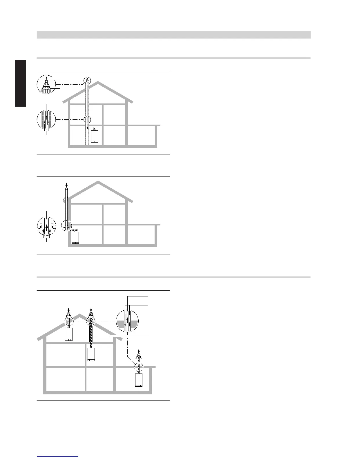
In an installation room with one or more full storeys above
A
Flue gas
B
Ventilation air
Routing through a shaft (type C
63x
or C
63
, to TRÖI 2009)
The boiler draws combustion air from the atmosphere through the
annular gap inside the shaft (chimney) and expels the flue gas via the
flue pipe above roof level.
The shaft is not part of the standard delivery. For a detailed description,
see pages 26 to 28.
Retrofitted shaft
For installation into a retrofitted, Building Regulations-approved shaft
made of shaft elements or mineral profiles.
For a detailed description of shafts, see page 18.
A
Flue gas
B
Ventilation air
Routing over external walls
(type C
53x
or C
53
, to TRÖl 2009)
The boiler draws combustion air from the atmosphere via a horizontal,
concentric coaxial pipe on the external wall and expels flue gas to the
atmosphere via the roof.
In its vertical section, the outside pipe of the concentric coaxial pipe
acts as thermal insulation thanks to its static air gap.
The combustion air is supplied via the balanced flue air inlet.
For a detailed description, see page 29.
In an installation room immediately below the roof or with only the roof space above
A
Flue gas
B
Ventilation air
C
Protective pipe against mechanical damage
Vertical outlet, if no shaft is available
(type C
33x
, to TRÖl 2009)
(various options)
1
Direct, vertical roof outlet through a pitched roof
2
Indirect, vertical roof outlet through a pitched roof with protective
pipe inside the attic space (if not converted) or fire protection
brickwork (if attic converted)
3
Direct, vertical roof outlet through a flat roof
The boiler draws combustion air from the atmosphere and expels flue
gas to the atmosphere via a concentric coaxial pipe through the roof.
For a detailed description, see page 32.
Flue systems
(cont.)
8
VIESMANN
VITOLADENS, VITORONDENS
1
5822 452 GB

 Loading...