4.6System design6
80
VITOSOL
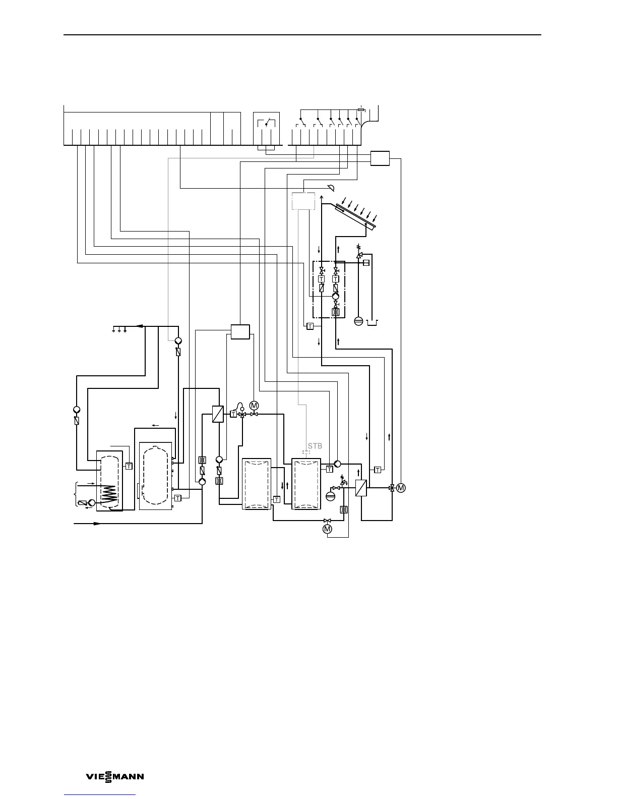
Installation diagram
*1
Wiring diagram see page 81.
A Solar panel
B DHW circulation pump
C To the oil/gas fired boiler
D DHW cylinder2
E DHW cylinder1 VitocellL
(pre−heating stage)
F Heat exchanger2
G Heating water calorifier2
H Heating water calorifier1
K Heat exchanger1
L Junction box (on−site)
Note regarding heat exchanger1
You can install a three−way diverter
valvewW to prevent frost damage.
Control by Vitosolic200. Sensor at S3 can
be utilised. This sensor is allocated to the
thermostat function5 via code; the valve
is switched via relay7.
5822135 GB
H
B
E
G
C
KW
*1
D
6
4
wQ
qP
qQ
qU
wP
3
9
8
qW
7
K
qT
qR
qI
F
qE
qO
A
2
VL
RL
5
qZ
L
GND
S1
S2
S3
S4
S5
S6
S7
S8
S9
S10
S11
S12
CS10
−−−−
Imp1
Imp2
145
145
R4
LN
R6−A
R6−R
R5−R
R5−A
R3
R2
R1
R7−A
R7−M
R7−R
1
2
1
21
1
2
WW
wW
*1
qZ
 Loading...