20
Section C – Power Unit Mechanism
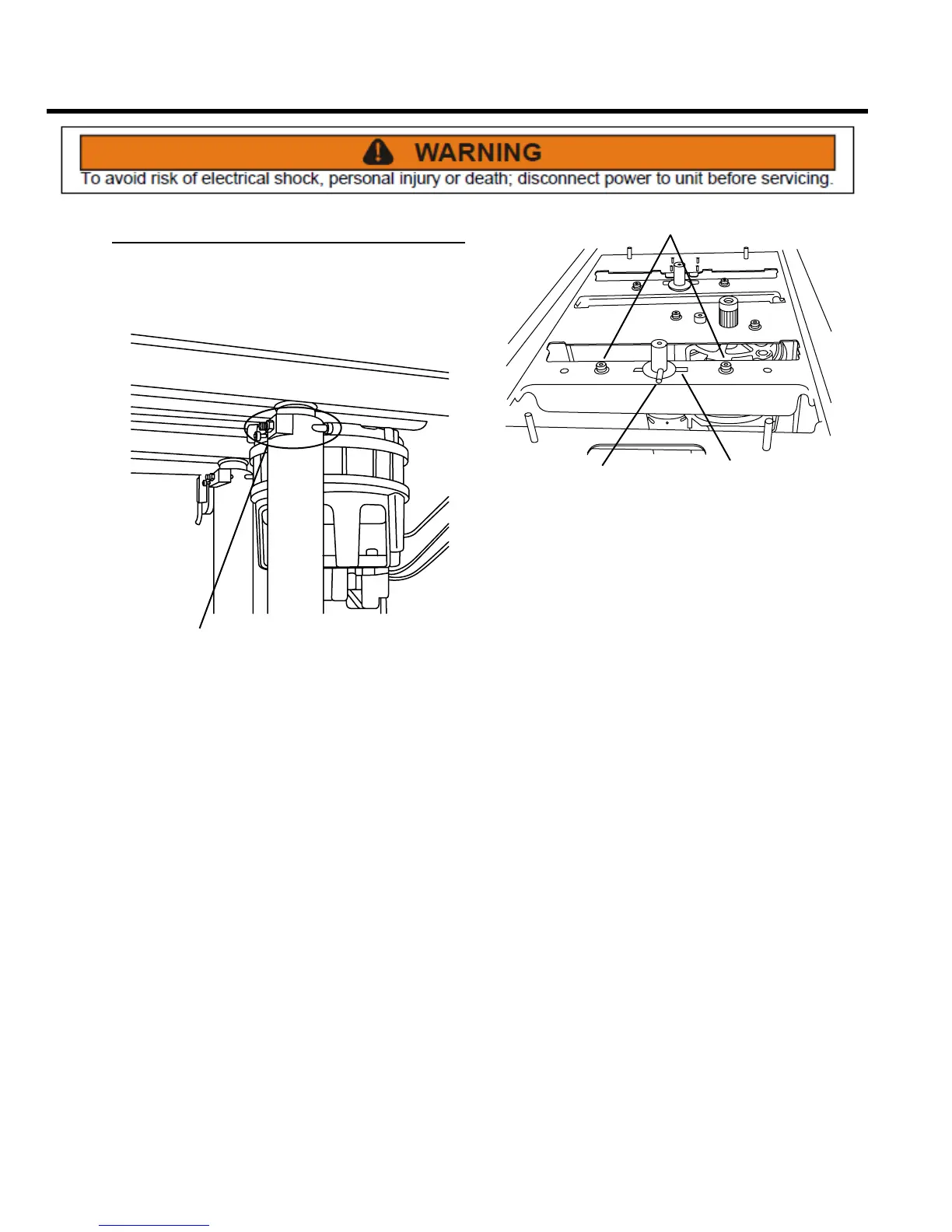
Ram Screw Assembly
REMOVE AND REPLACE
Once the compression plate assembly is removed,
continue with ram screw removal and disassembly.
FASTENERS
1. Remove two hex head screws, shims, brackets
and nuts (fasteners) from the top of the ram screw
assembly. Note orientation of bracket during removal
as they activate the limit switches.
PIN
FASTENERS
PIN
SLOT
2. Turn the ram until the top pin indexes 90° from the
pin slot; remove two hex screws, lock washers and
at washers (fasteners).
3. Turn the ram as required to align the ram pin with the
slot in the top frame and lower the ram through the
hole.