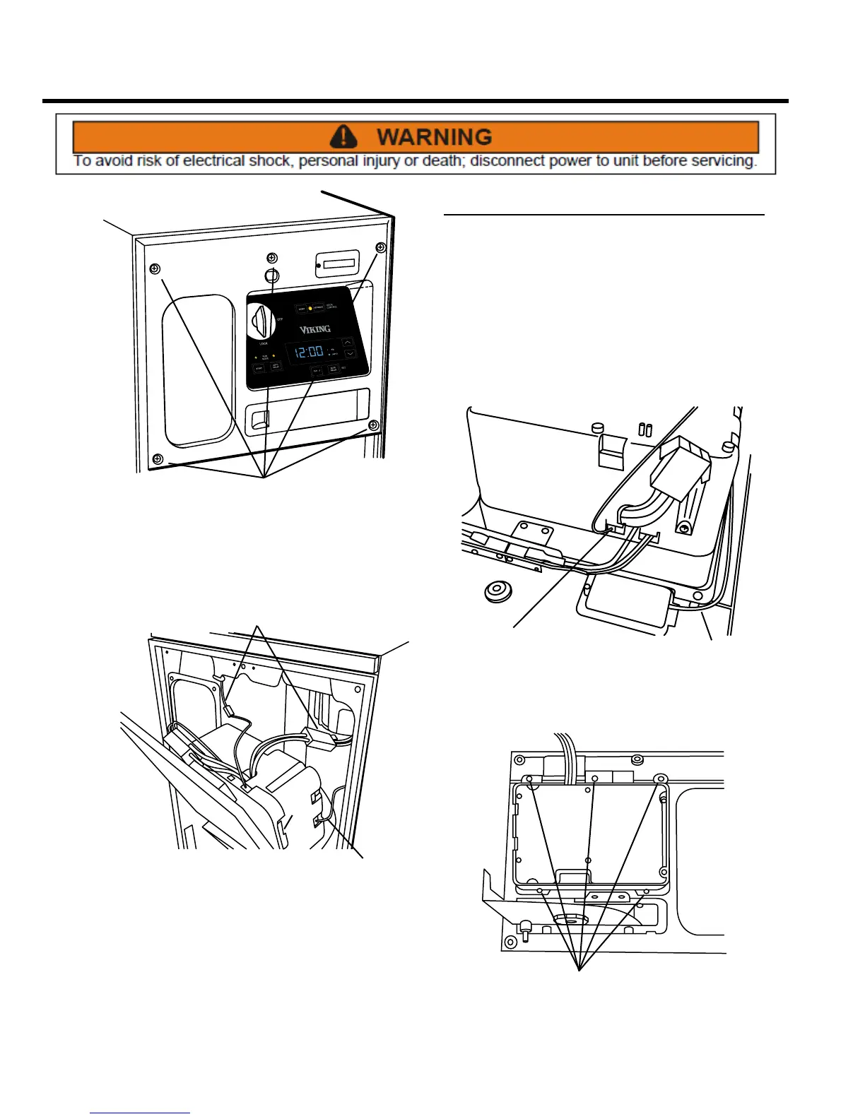
26 Section D – Electrical Components
SCREWS
1. On the front of the unit, remove the ve Phillips head
screws that secure the control panel assembly to the
cabinet cover.
WIRING
HARNESSES
WIRING
HARNESSES
2. After removing these ve screws, pull the panel away
from the cabinet and disconnect the three wiring
harnesses.
3. Installation is the reverse of removal.
Display Module Assembly
REMOVE AND REINSTALL
The display module assembly contains switches and LEDs
that allow the operator to turn the compactor ON and
OFF, and to place it in LOCK mode; to select HOLD or
NORMAL mode; to start the compactor cycle; to set the
clock and delay mode; and to monitor odor control, and
to reset and advance the odor control disk. If LEDs or
switches are worn, replace the display module.
1. Remove the control panel assembly from the unit (see
Control Panel Assembly, Remove and Re-install).
BATTERY
CONNECTOR
ODOR DISK
SWITCH
2. Disconnect the battery connector and odor disk
switch from the control panel.
SCREWS
3. Remove ve Phillips head screws and the display
module assembly from the control panel.
4. Installation assembly is the reverse of removal. NOTE:
First install display module assembly to panel, then
re-attach wiring.