29
Section D – Electrical Components
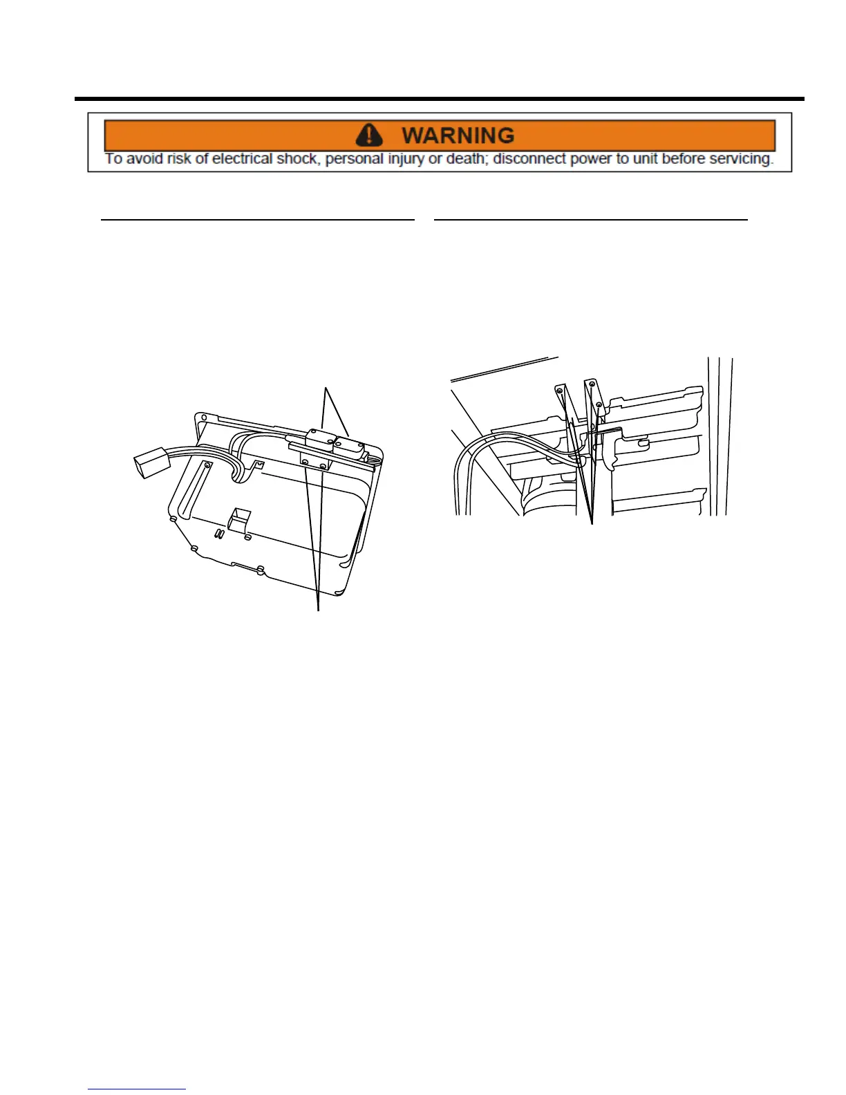
Interlock Switch Assembly
REMOVE AND REINSTALL
The interlock switch assembly is a safety feature. The
switch prevents the compactor from operating unless the
door is safely closed.
1. Remove the control panel assembly from the unit (see
Control Panel Assembly, Remove and Re-install).
SCREWS
WIRES
2. Noting their locations, transfer the wires to the
replacement switch assembly.
3. Remove two Phillips head screws and the interlock
switch assembly from the display panel.
4. Installation is the reverse of removal.
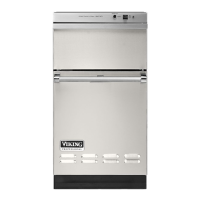
Upper Limit Switch Assembly
REMOVE AND REPLACE
This switch sets the upper travel limit for the ram
mechanism.
1. Remove the back panel from the cabinet cover (see
Access to Components, Remove Cabinet Cover).
SCREWS
2. Remove four Phillips head screws that secure the
switch assembly bracket to the top frame, and
remove the switch assembly.
3. Noting their locations, transfer the wires to the
replacement switch assembly.
4. Install the switch assembly and secure with four
Phillips head screws.